
jk electrical lighting sound systems
In an electronic schematic, the integration of relays into a lighting circuit is a common practice to enhance efficiency and safety. The relay acts as an intermediary switch that allows a low-current control signal to operate a high-current load, such as automotive lights.
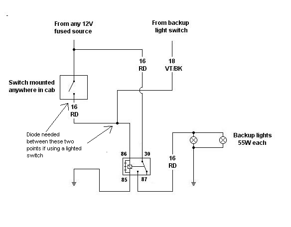
The typical relay configuration consists of four main terminals: two for the coil and two for the switch contacts. The coil terminals are connected to the control switch, which activates the relay when closed. The switch contacts are connected to the power supply and the load (in this case, the lights). When the control switch is activated, current flows through the coil, creating a magnetic field that closes the switch contacts, thereby allowing current to flow from the power supply to the lights.
The relay's placement should be as close to the lights as possible to minimize the distance that high-current wires must travel. This minimizes voltage drop and enhances light output. The use of appropriately rated wire gauges is essential; for example, 16 or 14 gauge wires may be used based on the anticipated current load. The relay should also be rated for the total current draw of the connected lights to ensure safe operation.
In terms of safety, a fuse should be placed in line with the power supply to the relay to protect against short circuits or overload conditions. Additionally, the relay should be mounted securely to prevent vibration from causing disconnections. Proper insulation and strain relief should be implemented at all wire connections to prevent wear and potential failure points.
Overall, implementing relays in automotive lighting systems not only simplifies the wiring process but also enhances the reliability and safety of the electrical system.By using a relay, you shorten the distance that you must pull the thick wires (especially through the firewall and under the dash), and you reduce the need for a larger switch. However, having said that, if you plan to connect to any of the stock JK electrical wiring (such as wiring them to the stock switch), then you must pay careful attention to what current levels the JK is expecting on that wire
else you cause unexpected failures. IOW: If the JK is expecting 100 milliamps (and I made up that number), don`t try to wire two 100-watt bulbs directly on that circuit. You may blow a fuse, you may cause the computer to croak, you may burn up wiring, or any of a lot of other bad things.
I`ve never put in a relay before, but maybe it`s just worth it to do so just for the efficiency of the deal, but I was curious if I could run all four lights without a relay, that would be the easiest solution as far as installation was concerned. 2007 Steel Blue 2Dr | 3" Full-Traction Lift | 35" Mickey Thompson Baja Claws | RR Modular Front Bumper | Smittybuilt Rear Bumper with Tire Carrier | Mopar Advanced Rock Rails | Body Armor Jerry Can Holder | Safari Straps For each set of lights you should use one relay.
First it will make the lights brighter. No matter how thick the wire is it will have a amount of resistance to it. The longer the wire the more resistance it will have. The relay is like a remote switch and moves the connection between the lights and the battery closer together. The shorter the wire distance from the light to the battery the brighter the light will be. This is one of the reasons why relays are used. The second reason is safety. If you do not use a relay and you have to much draw from the lights being on the entire length of the wire could heat up and the insulation could melt and then it will be a fireworks show if the fuse doesn`t blow.
08 Rubi Ultd | TERAFLEX 3" Lift & Frt Trk Bar | Rancho RS9000XL wMyRide | Stone White 16" PC 1079 and 35" GY MTR Kevlar`s | Cobra 29 w/ Cool Tech mnt. | Mopar Htd Seats | "Rescue" badges | Flashpaq w XDI CAI | Woods Hood Lift & Rear Door Shock & SS reloc kit | Gibson Quad Tip SS | Headers |MyGIG Lockpick wMic & RV cam | True HID Bi-Xenon Head and Fog 6000K | Viair HD OBA | Riddler FR Diff Cvrs | Full LED Conversion Two 100-watt bulbs will draw about 17 amps.
So the switch will be fine. However, that`s a lot of current draw, and if you don`t use a relay you`re running those thick wires for much longer-which means you need even larger wire to prevent power loss and overheating from voltage drops. Depending on the rating of the insulation, you`re probably looking at 16, maybe even 14 gauge wire. It`s not battery cable by any means, but it`s stout, stiff stuff. Difficult to work with, especially when you`re bringing it through the firewall and up under the dash and trying to get it to wherever that switch will be located.
I wouldn`t want to run it. A relay will make your install easier. As for running an extra pair of bulbs on that switch: Too much current, which means the switch will overheat. And, the wire size is unbelievably difficult to work with. But, put in a relay with terminals rated at that current and you`ll be good to go with even a light-duty switch (as long as it handles the relay`s coil current-the current it takes to operate the electromagnet in
🔗 External reference
Related Circuits
Surround Sound Decoder circuit diagram. The circuit's operation begins when the stereo sound signal carries surround sound information through the master volume section. This drives the Left channel (Lch), which is connected to Model TL072 IC1A and IC1B, with...
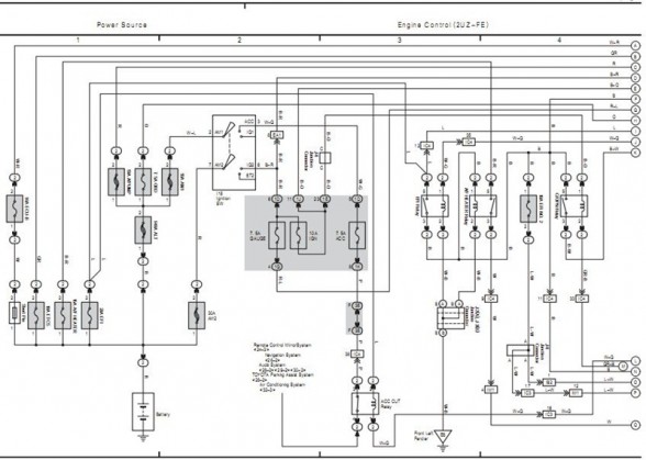
The following circuit illustrates the electrical circuit diagram for the 2006 Toyota 4Runner. It includes specifications related to the Toyota vehicle and details on safety features. The electrical circuit diagram of the 2006 Toyota 4Runner serves as a comprehensive representation...
The particular circuit does not have the requirement to replace the trade decoders Surround, because they have many more facilities and possibilities. It gives, however, the possibility in many trials with this article of decoding. The coding in Stereo...

This is a simple toggle switch that can be operated through sound signals such as a whistle or clap. The output of the toggle remains either low or high until... This circuit utilizes a sound sensor to detect specific audio...
The consumer unit cupboard in some older houses is poorly illuminated. If a bell transformer is also situated in this cupboard, it can be utilized to provide emergency lighting using two high-current LEDs. These diodes are powered through a...
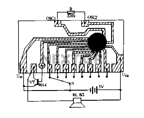
Constantly changing light and sound analog controller circuit 05 The circuit described is an analog controller designed to modulate light and sound in a dynamic manner. This type of circuit typically employs a combination of resistors, capacitors, and operational amplifiers...