
Keyboard Interfacing to 8051

The matrix keyboard interface with the 8051 microcontroller operates on the principle of scanning rows and columns to identify key presses. The matrix configuration allows for a compact design, where multiple keys can be monitored using fewer pins. In this setup, two ports of the microcontroller are dedicated to the keyboard matrix: one for output (to drive the rows) and one for input (to read the columns).
When a key is pressed, it creates a connection between a specific row and column, thus generating a unique signal that can be detected by the microcontroller. The scanning process begins by setting one of the row pins high while keeping the others low, effectively energizing that row. The microcontroller then checks each column pin in sequence to see if any of them are also high, indicating that a key in that row has been pressed.
The detection mechanism uses a counter to rotate the input port contents until a high signal is detected, signaling the presence of a pressed key. The accumulator's contents are manipulated to facilitate this detection, ensuring that the exact key pressed can be identified and subsequently displayed.
For visual output, a seven-segment display is employed, driven by a BCD to seven-segment decoder IC 7447. This decoder translates the binary-coded decimal output from the microcontroller into a format suitable for the seven-segment display, enabling the user to see which key was pressed in real-time.
This design leverages the capabilities of the 8051 microcontroller effectively, utilizing its I/O ports to manage input and output operations efficiently while maintaining a user-friendly interface for key press identification. The overall architecture is robust, allowing for easy expansion or modification, should additional features or keys be required in future applications.The key board here we are interfacing is a matrix keyboard. This key board is designed with a particular rows and columns. These rows and columns are connected to the microcontroller through its ports of the micro controller 8051. We normally use 8*8 matrix key board. So only two ports of 8051 can be easily connected to the rows and columns of the key board. When ever a key is pressed, a row and a column gets shorted through that pressed key and all the other keys are left open. When a key is pressed only a bit in the port goes high. Which indicates microcontroller that the key is pressed. By this high on the bit key in the corresponding column is identified. Once we are sure that one of key in the key board is pressed next our aim is to identify that key. To do this we firstly check for particular row and then we check the corresponding column the key board.
To check the row of the pressed key in the keyboard, one of the row is made high by making one of bit in the output port of 8051 high. This is done until the row is found out. Once we get the row next out job is to find out the column of the pressed key. The column is detected by contents in the input ports with the help of a counter. The content of the input port is rotated with carry until the carry bit is set. The contents of the counter is then compared and displayed in the display. This display is designed using a seven segment display and a BCD to seven segment decoder IC 7447. The 8051 has 4 I/O ports P0 to P3 each with 8 I/O pins, P0. 0 to P0. 7, P1. 0 to P1. 7, P2. 0 to P2. 7, P3. 0 to P3. 7. The one of the port P1 (it understood that P1 means P1. 0 to P1. 7) as an I/P port for microcontroller 8051, port P0 as an O/P port of microcontroller 8051 and port P2 is used for displaying the number of pressed key.
If any key pressed is found, the [accumulator] content is rotated right through the carry until carry bit sets, while doing this increment the count in the counter till carry is found. 🔗 External reference
Related Circuits
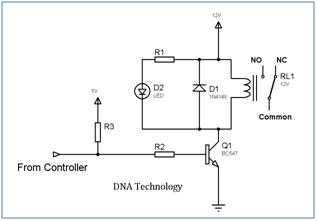
Relays are devices which allow low power circuits to switch a relatively high Current/Voltage ON/OFF. For a relay to operate a suitable pull-in & holding current should be passed through its coil. Generally relay coils are designed to operate...
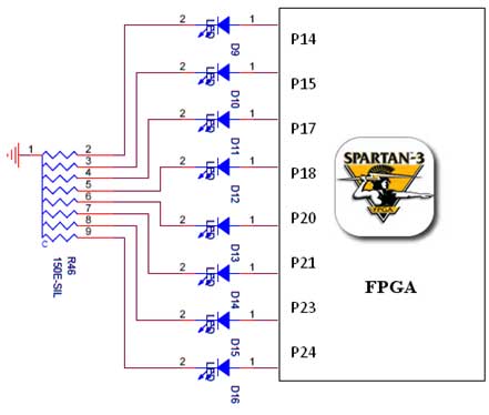
The Spartan-3 board features eight LEDs connected to FPGA I/O pins, with the cathode of each LED connected to ground through a 330-ohm resistor. To illuminate a specific LED, the corresponding FPGA control signal must be driven to a...
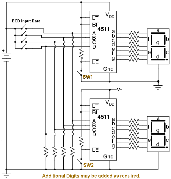
In industrial PLC applications, one of the older yet simpler methods of displaying numeric information involves utilizing one or more 7-segment numeric displays connected to an output card of a PLC. While it is feasible to construct such a...
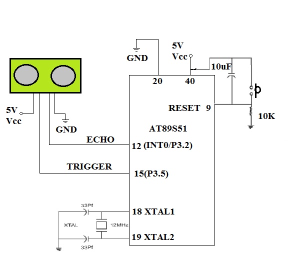
To enable a robot to detect objects in its surroundings, an ultrasonic sensor is recommended. While infrared (IR) sensors are inexpensive, their operational range can fluctuate due to ambient light changes, resulting in inaccurate range measurements. Ultrasonic sensors operate...

The circuit diagram for the receiving portion of a 2.4 GHz wireless keyboard is presented below. The 2.4 GHz wireless keyboard receiving circuit typically consists of several key components that work together to receive and process signals transmitted from the...
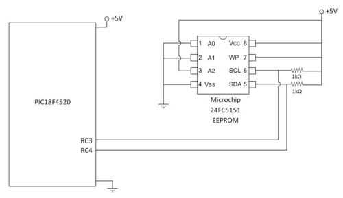
An external EEPROM is beneficial for various applications as it provides significantly more storage capacity than the internal memory of the 18F4520 microcontroller. Additionally, EEPROM retains its data even when power is disconnected. This project involves interfacing with a...