
Knight Rider Circuit
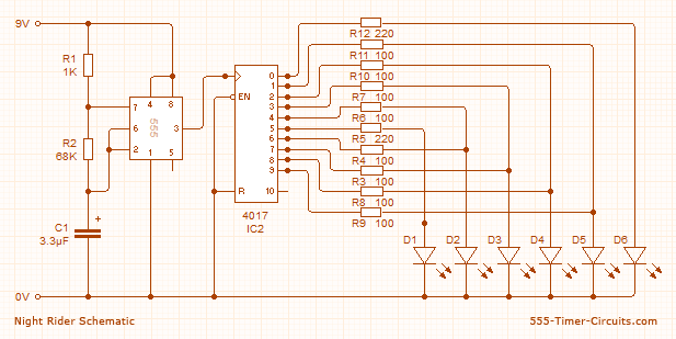
The circuit utilizes six 3mm red LEDs, which can be arranged at the front of a model car to create a realistic lighting effect. Additionally, the outputs can be interfaced with driver transistors to control a larger display. The overall circuit draws 22mA, with each LED receiving around 7mA. The outputs interact through the 100Ω resistors, except for Q0 and Q5, which do not interfere with each other. The parts list includes: 1 NE555 bipolar timer, 6 red LEDs, 8 resistors of 100Ω (1/4W), 2 resistors of 220Ω (1/4W), 1 resistor of 1KΩ (1/4W), 1 resistor of 68KΩ (1/4W), 1 electrolytic capacitor of 3.3µF (16V), 1 4017 decade counter, and 1 9V battery.
The Knight Rider circuit is an example of a simple yet effective electronic design that employs a 555 timer to generate a clock signal for the 4017 decade counter. The astable configuration of the 555 timer allows it to continuously oscillate, producing a square wave output that serves as the clock input for the 4017. This setup results in the sequential activation of the decade counter's outputs, which can be visually represented by the LEDs.
To ensure proper operation and prevent damage to the LEDs, it is critical to include current-limiting resistors. The choice of 100Ω or 220Ω resistors depends on the desired brightness of the LEDs and the available supply voltage. The interaction between the outputs is managed through these resistors, which help to balance the current distribution among the LEDs.
In applications where a larger display is required, the outputs from the 4017 can be connected to transistors that act as switches, allowing for higher current loads and more substantial lighting effects. This versatility makes the Knight Rider circuit suitable for various projects, including model cars and other decorative electronic displays.
The components listed in the parts list are readily available and can be sourced from most electronics suppliers. The design is straightforward, making it an excellent choice for hobbyists and those looking to learn about basic electronic principles, including oscillators, counters, and LED driving techniques.In the Knight Rider circuit, the 555 is wired as an oscillator (Astable mode). The output of the 555 is directly connected to the input of a 4017 decade counter. The input of the 4017 counter is called the CLOCK line. The 10 outputs Q0 to Q9 become active, one at a time, on the rising edge of the waveform from the 555. Each output can deliver about 20mA but a LED should not be connected to the output without a current-limiting resistor (100R or 220R).
Using six 3mm LEDs, the display can be placed in the front of a model car to give a very realistic effect. The same outputs can be taken to driver transistors to produce a larger version of the display. This circuit consumes 22mA while only delivering 7mA to each LED. The outputs are “fighting“ each other via the 100R resistors (except outputs Q0 and Q5). Parts list ::: 1x NE555 Bipolar Timer 6x LED (Red) 8x 100 Resistor (1/4W) 2x 220 Resistor (1/4W) 1x 1K Resistor (1/4W) 1x 68K Resistor (1/4W) 1x 3.3µF Electrolytic Capacitor (16V) 1x 4017 Decoded Decade Counter 1x 9V Voltage battery ....
🔗 External reference
Related Circuits
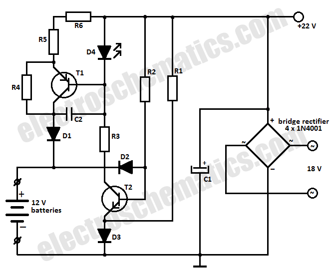
This battery charger circuit is designed to charge one or more batteries with a total nominal voltage of 12 V, which accommodates either ten NiCd batteries or six 2 V lead-acid batteries. The battery charger circuit operates by utilizing a...
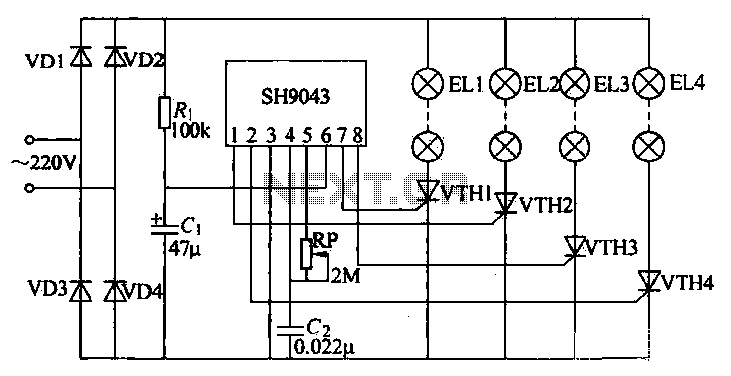
This example demonstrates a robust design featuring novelty lights that flash in a specific sequence, utilizing a 1-3-2-4 vault chase mode. The circuit includes diodes VD1 to VD4, which form a bridge rectifier, converting AC voltage to a full-wave...
This modified Hartley oscillator can be utilized to attract new friends or serve as a replacement doorbell. The modified Hartley oscillator is a type of electronic oscillator that generates a continuous waveform, typically a sine wave, using an LC (inductor-capacitor)...
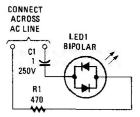
Many electronic circuits require an indication that they are powered. For most AC circuits, a neon lamp is the preferred device. A bidirectional tricolor LED can also be utilized if a capacitor is connected in series with the LED...
In this circuit, an LM339 quad voltage comparator is utilized to generate a time delay and control a high current output at low voltage. Approximately 5 amps of current can be sourced using a pair of fresh alkaline D...
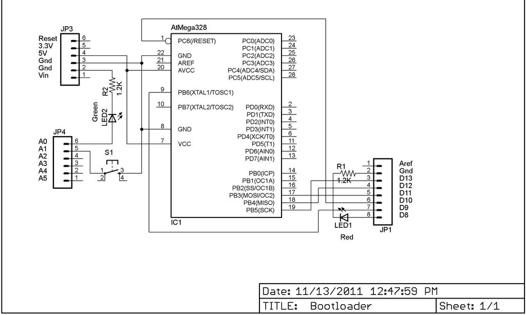
This Lazy Old Geek is also an Arduino enthusiast. One of the common microcontrollers used by Arduinos is the Atmega328 chip. To utilize Arduino software, the Atmega must be equipped with bootloader software. There is a notable difference between...