
TLV3702 Laser Pointer Sensor

The TLV3702 Laser Pointer Sensor Circuit utilizes the TLV3702 comparator to detect the presence of a laser beam, which can be employed in various applications such as robotics and automation. The circuit typically consists of a laser pointer that emits a beam directed towards a photodiode or phototransistor. When the laser beam strikes the photodiode, it generates a small current proportional to the intensity of the light, which is then fed into the TLV3702 comparator.
The TLV3702 operates on a single supply voltage, typically ranging from 2.7V to 5.5V, making it suitable for battery-powered applications. The output of the comparator can be configured to trigger various actions, such as starting a motor or activating another circuit element in response to the detection of the laser beam.
In a typical configuration, the circuit may include resistors to set the threshold voltage at which the comparator output switches states. This allows for fine-tuning the sensitivity of the laser detection. Additional components such as capacitors may be included to filter noise and stabilize the output signal.
The design may also incorporate an LED indicator that illuminates when the laser is detected, providing a visual confirmation of the sensor's operation. This circuit can be effectively integrated into robotic systems for navigation or object detection, enhancing the overall functionality and responsiveness of the robot.
Overall, the TLV3702 Laser Pointer Sensor Circuit is a versatile and efficient solution for applications requiring precise laser detection and control mechanisms.This circuit shows about TLV3702 Laser Pointer Sensor Circuit Diagram . Features: such as starting a robot, perfectly functional for controlling a .. 🔗 External reference
Related Circuits
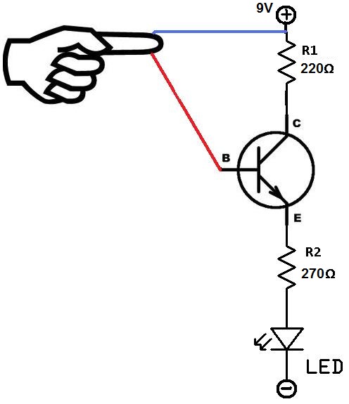
This project utilizes two wires, one red and one blue, which function as touch sensor wires. When a person touches both wires, the circuit closes, allowing current to flow and illuminate the LED. A 9-volt battery or an external...
For several years, a rear fog lamp has been mandatory for trailers and caravans to improve visibility in foggy conditions. When this fog lamp is activated, the fog lamp of the towing vehicle must be turned off to prevent...

The OPT301 is housed in a TO-99 8-lead package, offering good sensitivity with a bandwidth limited to 4 kHz. Its peak response is in the infrared region at 750 nm, while sensitivity in the visible red spectrum at 670...

This circuit diagram represents a laser communication system that transmits sound or music signals using a laser beam. The intensity of the laser beam varies in accordance with the amplitude of the sound signal. The variation in the intensity...

An automatic garage door opener, a seeded back lawn, a fireplace, and a refrigerator were offered. A flagpole was also requested, resulting in the installation of a 25-foot commercial flagpole. The owner has illuminated the flag at night to...

This circuit is a laser alarm system similar to those depicted in various movies. It employs a laser pointer beam to secure valuables and property. When the beam is interrupted by a person, animal, or object, the resistance of...