
LC meter 16x1 LCD Display
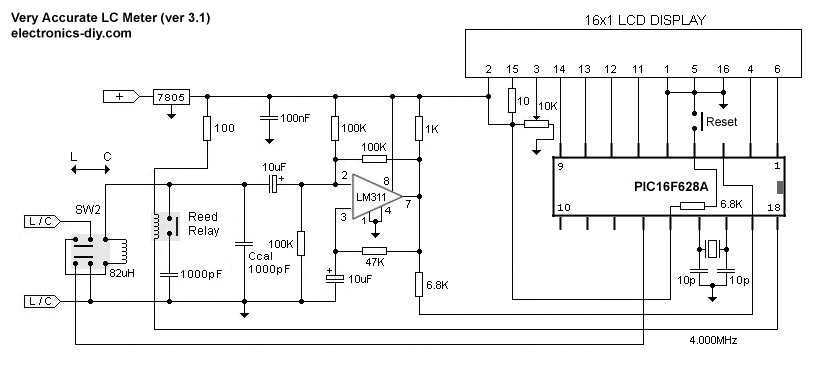
The LC meter circuit is designed to provide accurate measurements of inductance (L) and capacitance (C) over a wide range of values. The design typically incorporates a microcontroller or a dedicated integrated circuit (IC) that processes the measurement signals. The auto-ranging feature is implemented using a combination of analog switches and resistors, allowing the circuit to automatically select the appropriate range based on the detected signal level.
The operation of the LC meter relies on the resonant frequency formula, which is given by:
\[ f = \frac{1}{2\pi\sqrt{LC}} \]
Where:
- \( f \) is the resonant frequency in hertz (Hz),
- \( L \) is the inductance in henries (H),
- \( C \) is the capacitance in farads (F).
To measure inductance or capacitance, the circuit generates a known frequency signal which is then connected to the inductor or capacitor under test. The microcontroller measures the frequency shift caused by the component and calculates the value of L or C using the above formula.
The "Zero Out" switch is a critical feature for ensuring measurement accuracy. When activated, it allows the user to eliminate any parasitic capacitance or inductance that may affect the readings, thus enabling more precise measurements of the component in question.
The design may also include an LCD or LED display for easy reading of the measured values, and a power supply circuit that ensures stable operation of the meter. The overall layout of the circuit should be optimized for minimal noise and interference, which can be achieved through careful component placement and the use of shielding techniques if necessary.
In summary, the described LC meter is a versatile tool for electronics enthusiasts and professionals alike, providing a compact and efficient means to measure inductance and capacitance with high accuracy.This is one of the most accurate and simplest LC inductance / capacitance Meters that one can find, yet one that you can easily build yourself. This LC Meter allows to measure incredibly small inductances starting from 10nH to 1000nH, 1uH to 1000uH, 1mH to 100mH and capacitance from 0.1pF up to 900nF.
LC Meter`s circuit uses an auto ranging system so that way you do not need to spend time selecting ranges manually. Another neat function is the "Zero Out" switch that will reset the initial inductance / capacitance, making sure that the final readings of the LC Meter are as accurate as possible.
To be able to determine the value of an unknown inductor / capacitor we can use the frequency formula given below. Note that there are three variables that we can work with; f, L and C (f represents a frequency, L inductance and C capacitance).
If we 🔗 External reference
Related Circuits
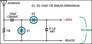
Many passive field strength meters have emerged in the past, typically utilizing a 50mA analog meter movement to achieve reasonable sensitivity. This circuit is similar but has the advantage of functioning with the high-impedance load of a digital multimeter,...
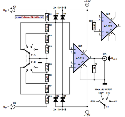
Unlike a standard voltmeter, an oscilloscope typically has one input terminal (GND) connected to ground through the mains lead. In specific situations... An oscilloscope is a vital instrument in electronics for visualizing voltage signals over time. It provides a graphical...
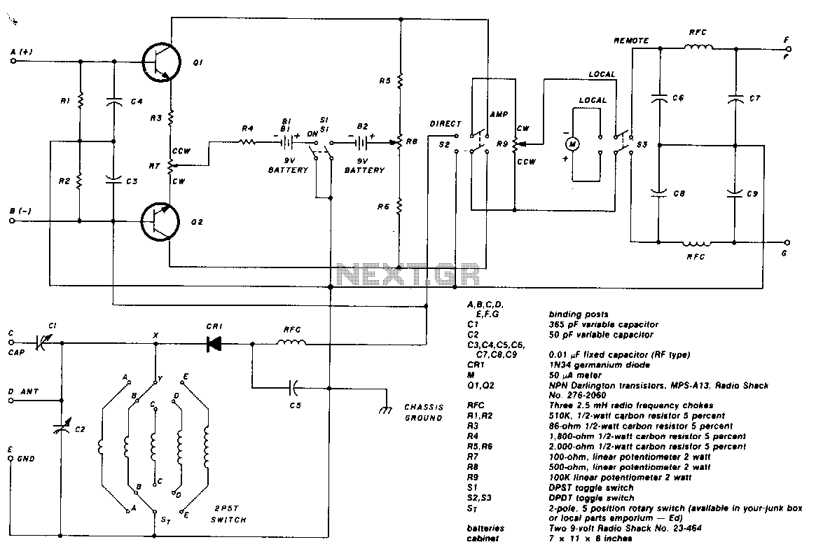
The two-pole, five-position switch, coils, and 365-pF variable capacitor cover a range from 1.5 to 30 MHz. The amplifier uses Darlington npn transistors whose high beta of 5000 provides high sensitivity, with SL used as the amplifier on/off switch....
Using the circuit of 40-metre band direct-conversion receiver described here, one can listen to amateur radio QSO signals in CW as well as in SSB mode in the 40-metre band. The circuit makes use of three n-channel FETs (BFW10)....
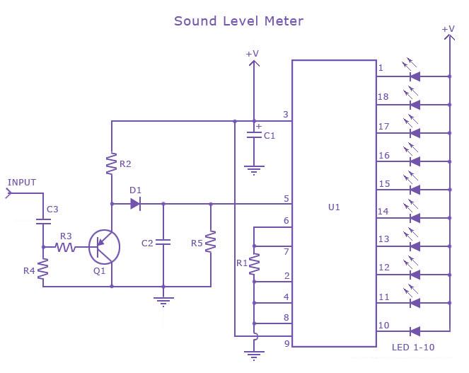
This is a single-chip sound level meter that can be used to display the sound level of an amplifier or simply the sound level from a microphone. The core component of the circuit is the IC LM3915 Audio Level...

I made this project as a test to improve a technique to read analog values without analog-to-digital converter (ADC). I ended with this "sound meter". It may not work perfectly, it needs some improvement but works anyway. It has...
Warning: include(partials/cookie-banner.php): Failed to open stream: Permission denied in /var/www/html/nextgr/view-circuit.php on line 713
Warning: include(): Failed opening 'partials/cookie-banner.php' for inclusion (include_path='.:/usr/share/php') in /var/www/html/nextgr/view-circuit.php on line 713