
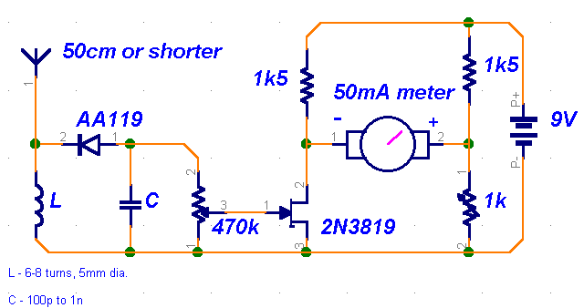
relative field strength meter
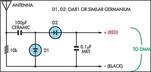
This circuit design serves as a passive field strength meter, intended for use with low-power communication devices. The key feature of this design is its compatibility with digital multimeters (DMMs), which typically have a high input impedance. This characteristic allows for accurate measurement of low-level RF signals without loading the circuit under test.
The circuit configuration includes a voltage divider and a rectifying stage, where the selected germanium diodes (such as OA81) serve to convert the RF signals into a DC voltage that can be measured by the DMM. The use of germanium diodes is crucial due to their low forward voltage drop and high sensitivity to low-level signals, making them suitable for detecting weak RF fields. While Schottky diodes can also be used, they may not provide the same level of sensitivity and accuracy, particularly in low-power applications.
The enclosure for the circuit should be compact, allowing for easy portability and use in field applications. The banana posts provide a convenient interface for connecting the circuit to the DMM, ensuring a secure and reliable connection. The antenna, which can be a simple length of wire, should be adjustable as needed to optimize reception of the desired RF signals. The recommended length of 500mm serves as a good starting point, but experimentation with different lengths may yield better results depending on the specific application and frequency range of interest.
This passive field strength meter is an effective tool for hobbyists and professionals alike, allowing for the measurement of RF signal strength in various low-power communication devices. Its simplicity and ease of use make it an excellent choice for those looking to assess the performance of their equipment in real-time.Many passive field strength meters have appeared in the past, typically using a 50mA analog meter movement if reasonable sensitivity was to be obtained. This circuit is similar but has the advantage that it works with the high-impedance load of a digital multimeter, typically switched to the 200mV range.
The sensitivity is adequate for low power e quipment like CB radios, cordless phones and model R/C sets (cars, model airplanes, etc). For best results, use OA81 or similar germanium diodes. Modern Schottky signal diodes could also be used but the results are not as good. The circuit can be wired directly into a small plastic box with protruding banana posts to match the terminals on your DMM. A banana jack can also be used for the antenna which could be just a 500mm length of wire as a starting point.
🔗 External reference
Related Circuits
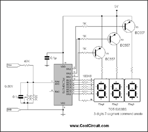
This is a simple 3-digit digital voltmeter. The PIC16F676 microcontroller is utilized to read an analog signal (voltage) and display the value on a 3-digit 7-segment display. It can also measure DC current using a parallel Rshunt, although that...

Noise level measured into 75ohm 3.1kHz BW using Siemens D2006 level meter: -80dBU (77.5mV) from zero to 1MHz and drops 3dB on 17MHz. Decrease the first coupling capacitor (68nF) to 10nF to increase the lower limit to 50kHz. The...
This capacitance meter circuit is similar to previous meter circuits, but it utilizes transistors instead of logic gates. A schematic diagram is provided. The capacitance meter circuit operates by measuring the capacitance of a capacitor through a time-based method. The...
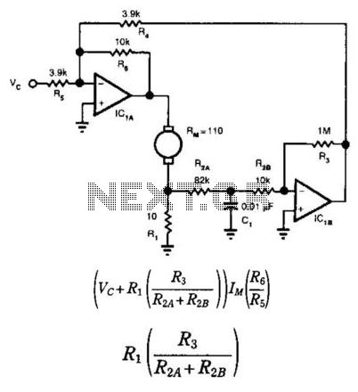
This circuit provides bidirectional speed regulation for small motors and does not require a tachometer. The voltage applied to the motor's windings, which is determined by summing amplifier IC1A, is expressed as a function of the command voltage (Vc)...
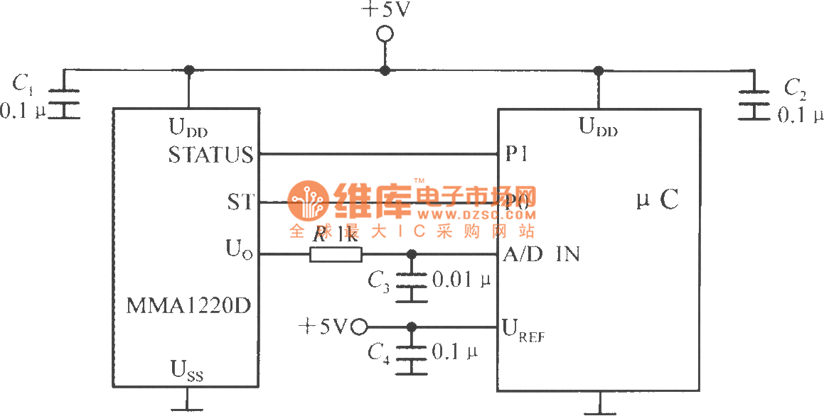
The microcontroller within the A/D converter can utilize a PIC MCU produced by Microchip. The MMA1220D's state and self-test pins are connected to the P1 and P0 ports of the microcontroller, with its output voltage sent to the input...
This is a straightforward circuit. The first stage functions as a crystal receiver, utilizing a germanium detector diode (such as 1N34, although AA119 is more commonly found in Europe); a silicon diode is not suitable. The operating frequency is...
Warning: include(partials/cookie-banner.php): Failed to open stream: Permission denied in /var/www/html/nextgr/view-circuit.php on line 713
Warning: include(): Failed opening 'partials/cookie-banner.php' for inclusion (include_path='.:/usr/share/php') in /var/www/html/nextgr/view-circuit.php on line 713