
LC Meter Circuit Coil Capacitor Meter
This LC meter circuit operates on the principle of frequency measurement, where the frequency of an oscillator is inversely related to the values of the connected inductors and capacitors. The heart of the circuit consists of an oscillator that generates a stable frequency signal. Upon connecting an inductor (Lx) or a capacitor (Cx), the load alters the frequency of the oscillator. The resulting frequency change is detected by a frequency-voltage converter, which translates the frequency shift into a corresponding voltage level. This is accomplished using two transistors, T3 and T4, which are configured to operate as a frequency-to-voltage converter.
The circuit includes two adjustable potentiometers, P1 and P2, which are used for fine-tuning the measurement accuracy. By adjusting these components, the user can calibrate the circuit to ensure that it provides precise readings. The stated precision of the LC meter is 3%, indicating that the measurements will have a maximum deviation of 3% from the actual values.
Calibration of the scale is essential for accurate readings and is achieved through the provided formula. The formula allows the user to determine the number of divisions on the scale (ni) based on the total number of divisions (nm) and the relative frequencies (fr and fc). This relationship is crucial for ensuring that the meter provides reliable and repeatable measurements across a range of inductance and capacitance values.
Overall, this LC meter circuit is a valuable tool for electronics enthusiasts and professionals, offering a compact and efficient solution for measuring inductors and capacitors with a reasonable degree of accuracy.This LC meter circuit can measure coils and capacitors. When Lx or Cx is connected in the circuit the oscillator frequency will decrease and this decrease is measured by a frequency-voltage converter build with T3 and T4. To adjust this lc meter circuit with P1 and P2. LC meter precision is 3%. Scale calibration can be achieved with this formula: ni = nm(1 fr)/(1 fc) where ni is number of divisions measured on the scale, nm = total number of division of the scale, fr = relative frequency, fc = the smallest relative frequency measured. 🔗 External reference
Related Circuits
The controller circuit illustrated in Figure 15-24 consists of a switch-type Hall integrated circuit DN838 and an astable multivibrator, which is based on the 555 timer IC. This circuit is suitable for various applications, including automatic door opening, delay...
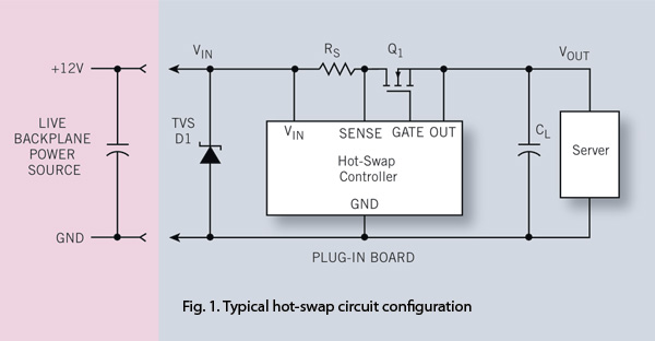
To ensure reliability, the server system designer must take into account the parasitics of hot-swap circuits and their associated transient behavior. It is recommended that a transient voltage suppressor (TVS) diode clamp be utilized at the line card input....
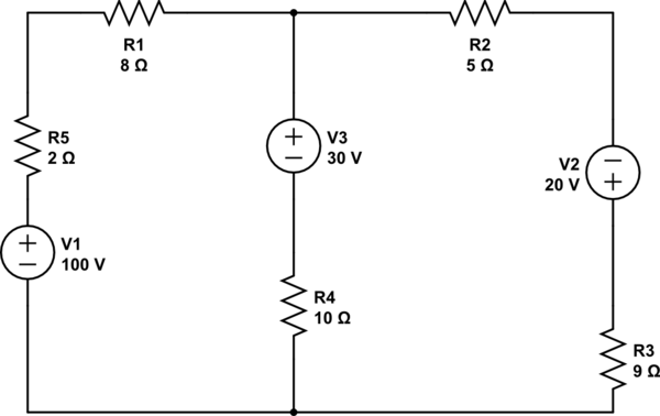
Using the superposition theorem, it is necessary to determine the current at all three nodes of the circuit. The current from the source, denoted as i_1, represents the current through V1 when other voltage sources are shorted out, in...
A sensitive and reliable RF field strength meter is an invaluable instrument in amateur radio and in the radio-controlled model area. A field strength meter is. A radio frequency (RF) field strength meter is a specialized device used to measure...
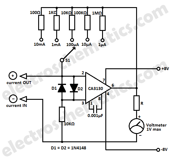
For those who labvoeding built and flow of tension and a leader in providing circuit below was developed. If meter is a moving-coil meter 100?A useful. You have to make yourself a new scale. Also useful is a moving...
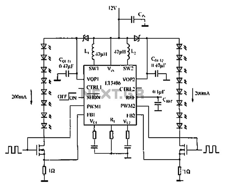
The automotive LED driver circuit diagram utilizes the LT3486. The LED is employed in the car's central high-mounted stop lamp (CHMSL), providing advantages such as faster achievement of the set brightness, higher efficiency, longer lifespan, and simplified design and...
Warning: include(partials/cookie-banner.php): Failed to open stream: Permission denied in /var/www/html/nextgr/view-circuit.php on line 713
Warning: include(): Failed opening 'partials/cookie-banner.php' for inclusion (include_path='.:/usr/share/php') in /var/www/html/nextgr/view-circuit.php on line 713