
Radio Control Motor speed Interface
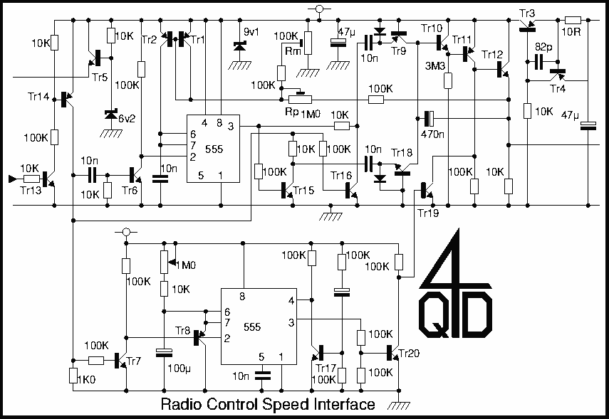
Tr13 and Tr14 are a level shifter and pulse conditioner to shape the radio receiver's output pulse. The shaped pulse is fed to the pulse length detector consisting of the first 555 with Tr15 and Tr16. The 555 (which provides a reference pulse) is triggered by Tr6 on the positive edge of the input pulse. Tr15's collector is high only when the input pulse is present and the 555 is off, so it gives a pulse output only if the input pulse length is longer than the reference pulse. Similarly, Tr16's collector is high only when the reference pulse is present but there is nothing on the input pulse. This pulse indicates reference is longer than the input.
Tr10 and Tr11 are a pump and hold circuit. Tr11 is operating at 90 microamps (9v, 100K) maximum so its base current is around 1/3 microamp (assuming a gain around 250). This base current is supplied via the 3M3 resistor (which is actually feeding 3 microamps - more than enough).
So under worst case conditions, Tr10 might have an emitter current of 3 microamps. Its base current is around 10 nano-amps. Assuming Tr9 and Tr18 are not conducting, this base current can only come from leakage or the 470n capacitor. This gives a discharge rate on the capacitor of around 20 millivolts/second. A hold time of around 30 seconds maximum is desired, with a 600mV drift considered acceptable. It can easily be improved with careful attention to detail, and it is also possible to use a JFET to remove the base current. The reference pulse generator (the 555) does not have a conventional timing resistor but rather a current mirror. The charging current flows from Tr2's collector and is equal to that flowing into Tr1. This input current has two components: a static part from Rm and a feedback component from the output via Rp. These two are adjustable and allow the pulse widths corresponding to maximum voltage (maximum pulse width) and minimum voltage (minimum pulse width) to be adjusted.
This circuit functions as a pulse width-to-voltage converter with a hold facility. The lower part of the circuit implements a timeout function. Each positive-going input pulse simultaneously triggers the timing cycle and clamps the timing capacitor to zero. The timer output goes high at the start of the pulse train but only starts its timing cycle at the end of the last input pulse. If no more pulses arrive before timeout, the timer completes its cycle and resets the output voltage to zero via Tr19, causing the golf caddy to stop.
The logic behind this design involves a small handheld transmitter with four buttons and a speed potentiometer. One button is designated for 'stop'—the circuit for this is not included above but will activate Tr19, stopping the machine. Another button is labeled 'refresh.' This button sends a string of pulses (width determined by the speed pot) to set the speed. The intention is for the user to press this button every 30 seconds or so to send the caddy off or maintain its progress. If the operator does not refresh the system in time, the timer will time out.
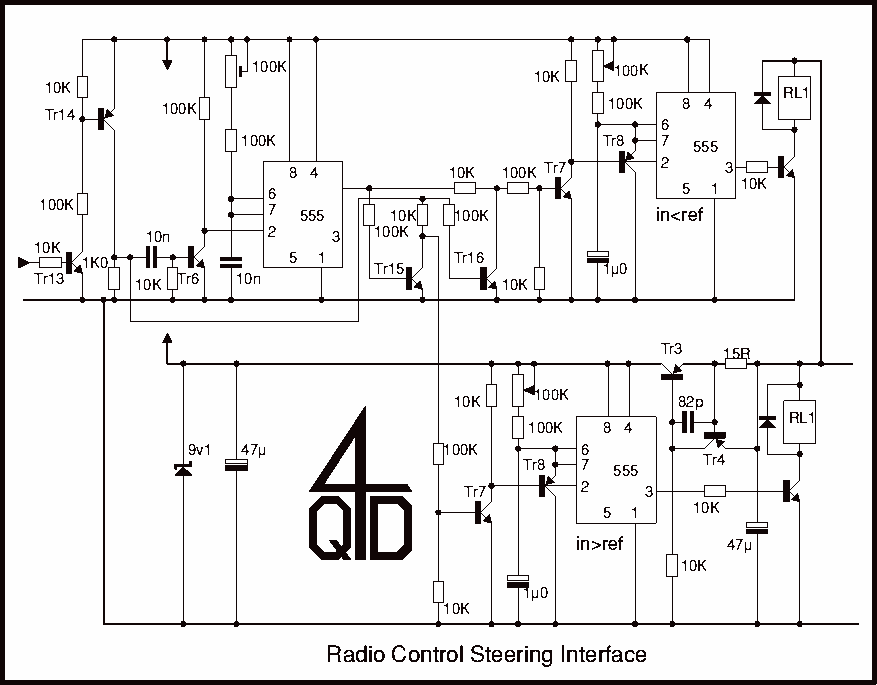
In the absence of any input pulse, there is no reference pulse, resulting in no pulses at the two 10n capacitors. The 470n capacitor slowly charges from leakage, and the output drifts towards zero volts. If an input pulse arrives, the reference pulse is triggered. If the reference pulse is too short, a positive pulse appears at the 10n capacitor feeding the emitter of Tr18. The 10n charges through the diode. When this pulse stops, Tr15 turns on, discharging the 10n. Since the diode is reverse biased, the capacitor can only discharge from Tr18's emitter. Tr18's emitter current is also its collector current, so the discharge pulse discharges the 470n capacitor, causing the output voltage to rise slightly.The second half controls the steering. The mechanical design is a 3 wheeled caddy with the ´single wheel´ actually a closely spaced pair of wheels which are driven by the main drive motor top provide motive power (this is the motor controlled by the first circuit). However the pair are on a motorised swivel arrangement: this second motor is the steering and can rotate the pair through 180 degrees, thus providing not only the steering but also the direction control.
Tr3 and Tr4 are a current source feeding a 9v1 zener to provide the internal supply. Tr5 with the 6v2 zener supply a 5.6 volt supply to the radio control receiver. This receiver gives two outputs - one is used for motor speed control and the other is used for the steering. Tr13 and 14 are a level shifter and pulse conditioner to shape the radio receiver´s output pulse. The shaped pulse is fed to the pulse length detector consisting of the first 555 with Tr15 and Tr16. The 555 (which provides a reference pulse) is triggered by Tr6 on the positive edge of the input pulse.
Tr15´s collector is high only when the input pulse is present and the 555 if off, so it gives a pulse output only if the input pulse length is longer than the reference pulse. Similarly Tr16´s collector is high only when the refernce pulse is present but there is nothing on the input pulse.
This pulse indicates reference is longer than the input. Tr10 and Tr11 are a ´pump and hold´ circuit. Tr11 is operating at 90 microamps (9v, 100K) maximum so its base current is around 1/3 microamp (assuming a gain around 250). This base current is supplied via the 3M3 resistor (which is actually feeding 3 microamps - more than enough).
So under worst case conditions Tr10 might have an emitter current of 3 microamps. Its base current is around 10 nano-amps. Assuming Tr9 and Tr18 are not conducting, this base current can only come from leakage - or the 470n capacitor. This gives a discharge rate on the capacitor of around 20 millivolts/second. We were after a hold time of around 30 second maximum and we considered a 600mV drift perfectly acceptable.
It can easily be bettered by careful attention to detail and it if also possible to use a JFET to remove the base current. Now the reference pule generator (the 555) doesn´t have a conventional timing resistor but rather, a current mirror (more information on current mirrors).
The charging current flows from Tr2´s collector and is equal to that flowing into Tr1. This input current has two components, a static part from Rm and a feedback component from the output via Rp. These two are adjustable and allow the pulse widths corresponding to maximum voltage (maximum pulse width) and minimum voltage (minimum pulse width) to be adjusted.
So we have a pulse width-to-voltage converter with a hold facility. The bottom part of the circuit is a timeout function. Each positive going input pulse simultaneously triggers the timing cycle and clamps the timing capacitor to zero. So the timer output goes high at the start of the pulse train but only starts its timing cycle at the end of the last input pulse.
If no more pulses arrive before timeout, the timer completes its time cycle and resets the output voltage to zero via Tr19 and the golf caddy stops dead. If the logic of this is a little obscure, the idea is is to have a small hand-held transmitter with four buttons and a speed pot.
One button is to be ´stop´ - the circuit for this is not included above but it will turn on Tr19, stopping the machine dead. Another button is ´refresh´. This will send a string of pulses (width determined by the speed pot) to set the speed. The idea is that the user pushes this every 30 seconds or so to send the caddy off, or to maintain its progress.
If the operator doesn´t refresh the system in time, the timer times out. So in the absence of any input pulse there is no reference pulse so no pulses at the two 10n capacitor. The 470n slowly charges from leakage and the output drifts towards zero volts. If an input pulse arrives the reference pulse is triggered. If the reference pulse is too short a positive pulse appears at the 10n capacitor feeding the emitter of Tr18.
The 10n charges through the diode. When this pulse stops Tr15 turns on, discharging the 10n. As the diode is reverse biased the capacitor can only discharge from Tr18´s emitter. Tr18´s emitter current is also its collector current, so the discharge pulse discharges the 470n capacitor and the output voltage rises a little. 🔗 External reference
Related Circuits
This document describes an efficient inverter control circuit designed for use as an LCD backlight power supply. The circuit is primarily managed by the chip UL (02962G), which interfaces with a driving field-effect transistor (U2), a voltage transformer, the...
An automatic recording telephone interface circuit is presented, featuring an automatic answering and recording function that requires a reprovisioning or a small solid-state recording chip. The circuit is straightforward, with a quiescent current of less than 20 µA, allowing...
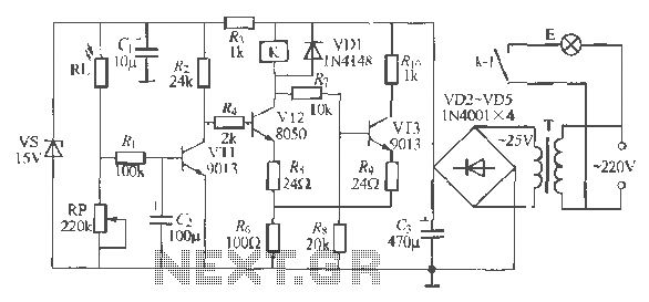
The circuit operates as a light-activated switch that controls white moving lights. It features high sensitivity, stable performance, and good anti-interference characteristics. A photosensitive resistor (RI) is employed to detect ambient light levels. During the day, the resistor exhibits...
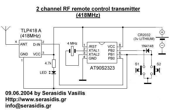
Remote controls are often needed to manage various electric devices. There are several types of remote controls available, including infrared, RF (Radio Frequency), and SMS. Basic short-range remote controls primarily utilize infrared and RF technology. A limitation of infrared...
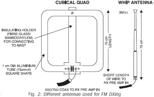
FM transmissions can be received within a range of 40 km. In fringe areas, the signal may be very weak. FM DXing refers to the practice of receiving distant stations (1500 km or more) on the FM band (88-108...
This low current relay circuit is designed for use in battery-operated electronic devices. Its operating current is in microamperes (µA). This is achieved by using a bistable relay and incorporating additional components to enable the relay to function like...