
LCD to LPT board

To JP2 you must apply 12V and if you wish you can add a polarity protection diode (1N4007).
For the IR receiver you must read the site http://www.lirc.org. The only thing i have to add up is to remove pin3 during contraction and read the receiver's IC datasheet to help you out connecting it right. An adaptor for the LCD is also included so you can use a ribbon cable for the connection with the main circuit.
The LCD2LPT with Lirc circuit integrates an LCD to LPT interface and an infrared (IR) remote control interface on a single PCB. The LCD interface employs a modified design that incorporates backlight and contrast control, facilitated through four push buttons. The DS1809 integrated circuits (ICs) from Dallas-Maxim semiconductors are central to this functionality, with two dedicated buttons for each adjustment. The first IC (IC1) manages the contrast of the LCD, utilizing push buttons S1 (for increasing contrast) and S2 (for decreasing contrast). The second IC (IC2) governs the backlight intensity, using buttons S3 and S4, and is augmented by a transistor (T1) to effectively control the brightness levels.
Power regulation for the circuit is handled by a 7805 voltage regulator (IC3), which ensures a stable 5V output necessary for the operation of the LCD and associated components. Additionally, a filtering capacitor is included in the design to mitigate transient voltage spikes, thereby protecting sensitive ICs from potential damage.
For power supply, a 12V input is required at the JP2 connector. To enhance circuit protection, the inclusion of a polarity protection diode, such as the 1N4007, is recommended.
The IR remote control functionality is designed to work with the LIRC software, which can be accessed for additional setup instructions. It is crucial to remove pin 3 during construction and to consult the datasheet of the IR receiver IC to ensure correct wiring and functionality. Furthermore, an adapter for the LCD is provided, allowing for a straightforward connection using a ribbon cable to integrate with the main circuit seamlessly.The "LCD2LPT with Lirc" circuit is the compilation of two circuits found on the net on a single board. The first is LCD to LPT interface and the second an IR remote control interface using http://www.lirc.org program.
The main circuit for LCD connection to LPT was modified adding a backlight and contrast control using 4 push buttons. Responsible for the adjustment are the two DS1809 ICs made from Dallas-Maxim semiconductors along with 2 buttons for each adjustment.
IC1 with the use of S1(+, Up) and S2(-, Down) controls the Contrast of LCD and IC2 with the use of S3(+, Up) and S4(- , Down) and the help of transistor T1, controls the backlight intensity. IC3 is a 7805 regulator that stabilize the power line of the circuit. There is also a filtering capacitor that helps the transient discharge of the circuit preventing any damages to the ICs. To JP2 you must apply 12V and if you wish you can add a polarity protection diode (1N4007). For the IR receiver you must read the site http://www.lirc.org. The only thing i have to add up is to remove pin3 during contraction and read the receiver's IC datasheet to help you out connecting it right.
An adaptor for the LCD is also included so you can use a ribbon cable for the connection with the main circuit. 🔗 External reference
Related Circuits
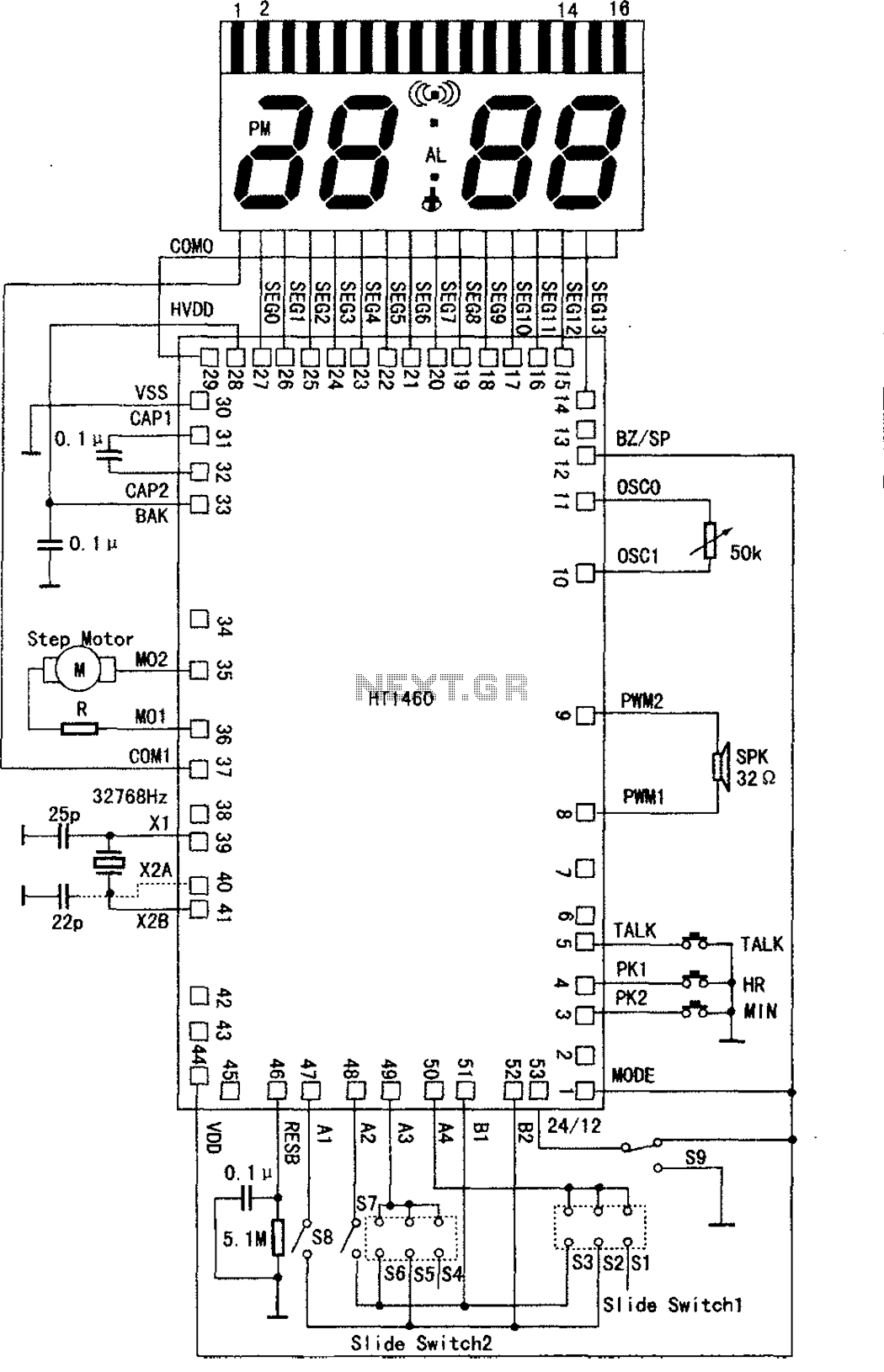
The speech synthesis circuit incorporates a microprocessor series, LCD drivers, a clock oscillator, input and output ports, memory, and a multi-voice audio signal amplifier circuit unit. This series circuit is primarily utilized in voice clocks, thermometers, electronic calendars, and...
U1 is a Complex Interface Adapter (CIA). Both parallel ports are utilized to decode the keyswitches on the keyboard. Parallel port A signals (PA0 - PA7) function as outputs, while parallel port B signals (PB0 - PB7) serve as...
The doorbell button was replaced with a lighted version, but the chime continued to sound after the button was pressed. These lighted buttons incorporate an incandescent bulb in parallel with the button, a component that has been modified in...
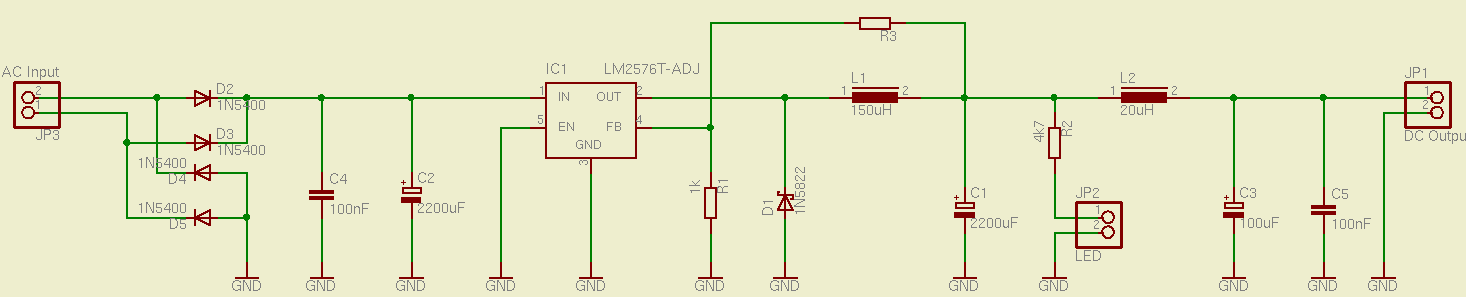
This is a simple and effective switched mode power supply (SMPS) designed to power an LCD monitor. It requires 20V at 2.3A, but the power supply unit (PSU) output voltage can be adjusted in the range of 1.2V to...
This data sheet describes the evaluation board for the AD9834 direct digital synthesizer (DDS). The AD9834 is a numerically controlled oscillator that utilizes a phase accumulator, a sine look-up table, and a 10-bit DAC. The AD9834 can operate with...

This article continues from the previous one regarding the single character LCD display using an AVR microcontroller. The prior article demonstrated how to display a single letter on an LCD. This article advances the learning process by explaining how...