
Lead acid battery charger
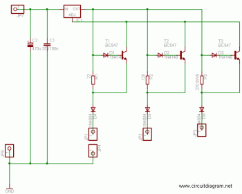
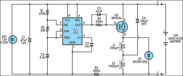
The schematic for this battery charging circuit features a straightforward design that effectively manages the charging process for a 12V lead-acid battery. The circuit begins with a 6-0-6V transformer that steps down the mains voltage to a lower AC voltage suitable for rectification. The output from the transformer feeds into a bridge rectifier, which converts the AC voltage to a pulsating DC voltage. Following this, a 4700µF smoothing capacitor is employed to reduce voltage ripple, providing a stable DC voltage to the LM317 adjustable voltage regulator.
The LM317 is configured to output a constant voltage of 13.75V, appropriate for charging the battery in standby mode. This output voltage is set using two resistors, which form a voltage divider that adjusts the reference voltage of the LM317. The regulator's features, including current limiting and thermal shutdown, ensure safe operation by preventing overheating and overcurrent situations, which could damage the battery or the circuit components.
This circuit is designed for simplicity and efficiency, requiring only six components, which include the transformer, bridge rectifier, smoothing capacitor, LM317 regulator, and two resistors. The compact nature of the design allows it to be easily assembled on a small veroboard or directly on the transformer, making it a practical solution for home battery charging applications. The absence of a heat sink for the LM317 regulator indicates that the design is optimized for low output currents, which is suitable for the charging requirements of a lead-acid battery in standby mode. All components can be sourced from Maplin, ensuring accessibility for those looking to construct this charging circuit.Battery manufacturers recommend charging 12V lead-acid batteries at a charge voltage of 13. 5 - 13. 8V for standby, and 14. 4 v - 15v for cyclic use(charging and discharging) - but if using the latter, which gives a faster charge, you must turn it off when fully charged. I use the 13. 8V option, and leave my battery charging until I need it - although it`s always fully charged after about 12H. The charger uses a LM317 adjustable regulator. This is an adjustable 3 terminal positive voltage regulator capable of supplying in excess of 1. 5 amps over an output range of 1. 25 to 37 volts. The device also has built in current limiting and thermal shutdown which makes it essentially blow-out proof. A 6 - 0 - 6V (or 12V) 6VA transformer feeds a bridge rectifier, and the signal is smoothed with a capacitor of 4700uF at any voltage above 16V.
This gives about 17. 5V to the regulator. The output voltage is set to 13. 75V by the two resistors. Only 6 components, it can be built as a birds nest on the transformer, or as I have on a little bit of veroboard. The 1A regulator doesn`t need a heat sink. All parts available from Maplin`s. 🔗 External reference
Related Circuits
Is the battery empty, or is there something wrong with the device? This question can be challenging when a battery-powered device, such as a Walkman, appears to be non-functional upon switching it on. Before seeking professional servicing, the initial...
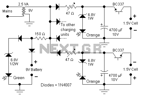
The following diagram represents the schematic of a Ni-CAD battery charger circuit, which features current and voltage limiting to prolong the battery's lifespan. The lamp L1 will illuminate brightly while the LED will be off when the battery is...
This circuit employs the widely used and easily accessible LM3914 integrated circuit (IC). The LM3914 is straightforward to operate, does not require external voltage regulators due to its built-in voltage regulation, and can be powered by a variety of...
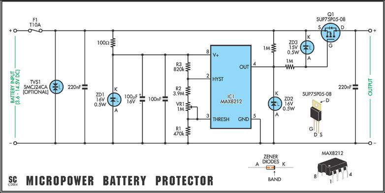
In May 2002, Silicon Chip introduced the "Battery Guardian," a project aimed at safeguarding 12V car batteries from over-discharge. This unit has gained significant popularity and remains available from kit suppliers. The new design does not replace the Battery...
Lead-acid batteries frequently experience premature failure due to overcharging, undercharging, deep discharging, and low electrolyte levels. These conditions can lead to the sulfation of the plates, resulting in high internal resistance and eventual battery failure. Typically, this sulfation process...
It is possible to reduce electricity bills by utilizing alternative power sources. The photovoltaic module, or solar panel, described here, can produce a power output of 5 watts. Under full sunlight conditions, the solar panel generates 16.5V and can...