
Lead Acid Battery Charger Circuit
The circuit designed for charging lead-acid batteries incorporates a current-limited power supply alongside a flyback converter topology to ensure efficient charging while protecting the battery from overcurrent conditions. The current-limited power supply serves as the primary source, providing a stable voltage output that is adjustable according to the battery's specifications.
The flyback converter topology is employed to convert the input voltage to a higher output voltage, which is necessary for charging the lead-acid battery effectively. This topology is advantageous due to its ability to isolate the input and output, ensuring safety and reducing the risk of back EMF damaging the power supply.
In the schematic, the power supply is connected to the flyback converter, which includes a transformer, switching elements (such as MOSFETs), and diodes. The transformer is responsible for stepping up the voltage, while the switching elements control the conversion process, allowing for efficient energy transfer. The output from the flyback converter is then fed into the battery through a rectifying diode to prevent reverse current flow, ensuring that the battery is charged correctly.
Additionally, the circuit may include various protective components such as fuses or circuit breakers to safeguard against short circuits and excessive current draw. A feedback mechanism can also be integrated to monitor the battery voltage and adjust the charging current accordingly, maintaining optimal charging conditions and prolonging battery life.
Overall, this circuit design effectively combines a current-limited power supply with a flyback converter for reliable and efficient lead-acid battery charging.To charge lead-acid batteries we can use this circuit that consist of a current-limited power supply and a flyback converter topology. Here is the schematic . 🔗 External reference
Related Circuits
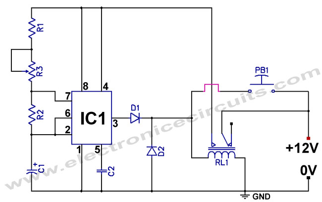
The standard 555 timer circuit consumes power from the battery even when the start push-button (PB1) is not pressed, due to a potential divider created by three 5kΩ resistors within the integrated circuit (IC). This power consumption, referred to...
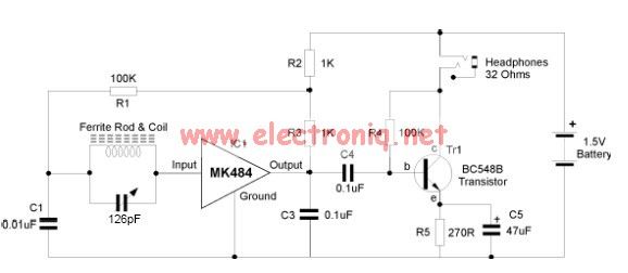
The MK484 AM radio circuit offers a comprehensive solution featuring an RF amplifier, detection, and an automatic gain control (AGC) circuit. It requires only a few external components to achieve high-quality AM tuning. The circuit has an input impedance...

This circuit is designed to provide automatic current limiting up to 8.4 A. Unlike traditional current limiters that rely solely on a resistor, this circuit minimizes voltage drop until a specified current threshold is exceeded. The current limit can...
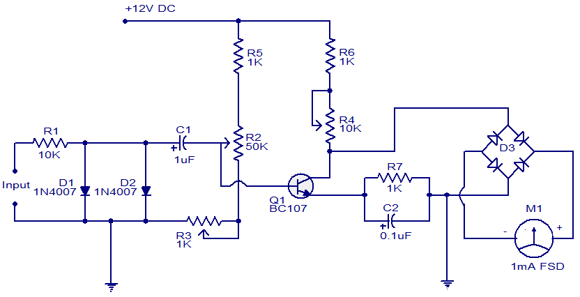
This is a simple circuit that functions as a tachometer. It operates as a frequency-to-current converter, transforming the incoming signal into a proportional current to drive the meter. The deflection on the ammeter correlates directly with the frequency of...
The motor switch control circuit depicted in the figure provides two speed settings for counter-steering, allowing for operation at two speeds in opposite directions. The motor switch control circuit is designed to facilitate the operation of a motor at two...
An FM modulator that modulates a carrier frequency with the composite signal, and an RF amplifier that provides enough power to be transmitted through an antenna. Here is the schematic diagram of the FM transmitter circuit: The core of...