
LED Driver with 555 Timer

The LED driver circuit described operates on the principle of boost conversion, allowing for efficient voltage amplification from a low-voltage source, specifically a single AA NiMH cell. The circuit typically includes a switching transistor, an inductor, a diode, and a capacitor.
When the circuit is activated, the transistor switches on and off rapidly, creating a pulsing current through the inductor. During the "on" phase, the inductor stores energy from the power source. When the transistor switches off, the inductor releases its stored energy, generating a higher voltage across the load, which in this case, is the array of LEDs.
The choice of a 220 µH inductor is crucial as it determines the efficiency and performance of the circuit. A larger inductance value would store more energy but may also slow down the switching frequency, while a smaller value may result in insufficient energy storage for the required output voltage.
The diode in the circuit prevents backflow of current, ensuring that the energy released by the inductor is directed towards the LEDs. A smoothing capacitor is often added to the output to reduce voltage ripple, providing a more stable voltage supply to the LEDs, which helps to enhance their brightness and longevity.
This circuit configuration is particularly advantageous for battery-operated devices, where maximizing efficiency and extending battery life are critical. By driving multiple LEDs with a single cell, this design is not only cost-effective but also compact, making it suitable for various portable applications.This simple LED driver circuit allows us to drive up to seven LEDs by using a single NiMH (Nickel Metal Hydride) AA cell. The circuit produces voltage pulses at a much higher level than the input supply voltage by pulsing the 220 uH inducto..
🔗 External reference
Related Circuits
Typically, an LED is powered by a DC supply; however, this circuit enables the LED to be powered by an AC supply. This circuit can serve as a power indicator for a water pump. The circuit for powering an LED...
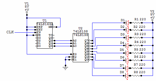
This is a very simple circuit to build, just take note of the control pins on each IC, since both have enable inputs for counting or output, but once set you don't need to worry about them. From left...
The clock circuit above uses seven ICs and 19 LEDs to indicate binary coded decimal time. The LEDs can be arranged so that each horizontal group of 3 or 4 LEDs represents a decimal digit between 0 and 9...
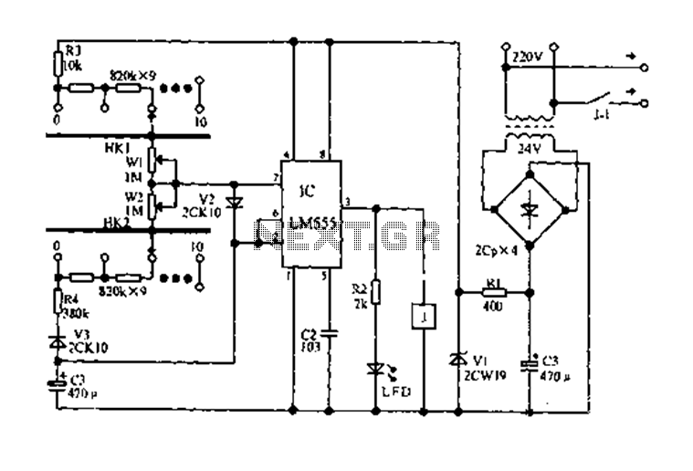
The circuit diagram for an electric start and stop timer is illustrated in the following cycle. It utilizes the LM555 integrated circuit configured as an adjustable duty cycle multivibrator. The circuit includes components C3, KH1, W1, KH2, and W2,...
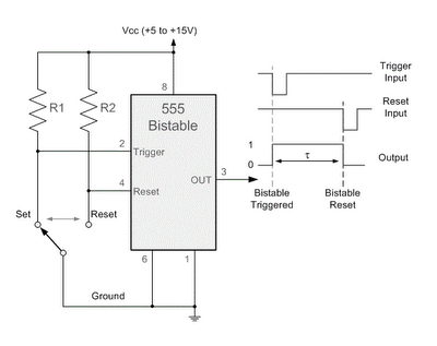
By applying a "LOW" signal to the Trigger input (pin 2) while the switch is in the Set position, the output state changes to "HIGH". Conversely, applying a "LOW" signal to the Reset input (pin 4) while the switch...
All LEDs require some form of current limiting. Connecting an LED directly to the power supply will burn it out almost instantly. Overdriving, even briefly, will significantly reduce its lifespan and light output. Fortunately, driving a single or a...