
Led Running Lights
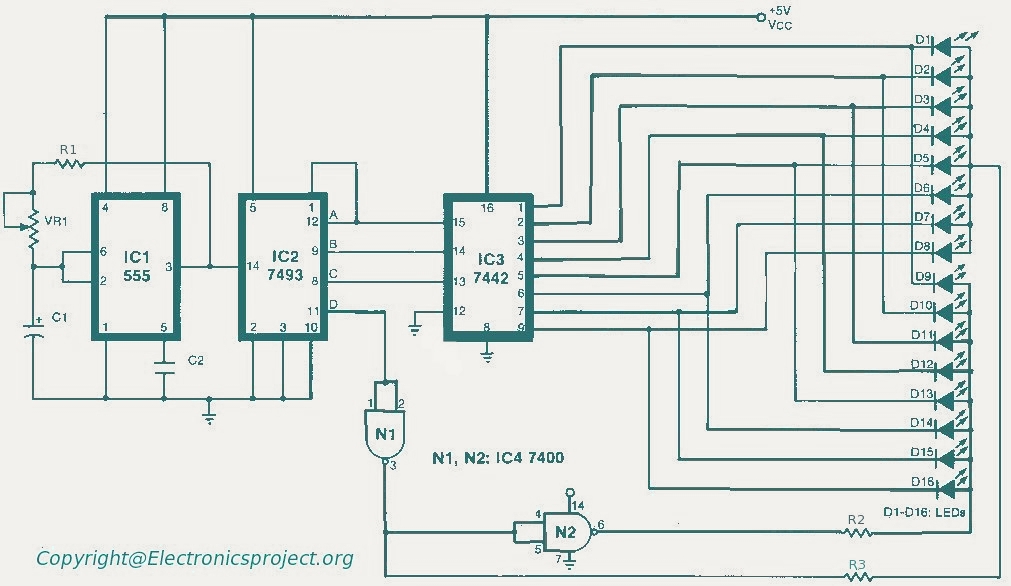
The circuit design can be divided into three distinct functional blocks: the oscillator, the mod 16 counter, and the LED driver section.
The oscillator is designed to operate in a self-triggered mode, which ensures continuous operation without the need for an external clock signal. The frequency of oscillation can be adjusted using the variable resistor (VR1), allowing for a broad range of frequencies. This feature is particularly useful for applications requiring dynamic light effects, as it enables the user to fine-tune the speed of the running lights.
The mod 16 counter (7493) serves as the core counting mechanism, producing binary outputs corresponding to its count value. The outputs A, B, and C are directly connected to the decoder IC3 (7442), which converts the binary count into a decimal output. The decoder outputs are available on pins 1 to 9, which can drive multiple LEDs, providing visual feedback of the counter's state.
The D output of the counter plays a crucial role in determining which set of LEDs is illuminated. The circuit is designed such that when the D output is low, it activates the first set of LEDs (D1 to D8). Conversely, when the D output is high, the second set of LEDs (D9 to D16) is activated. This dual selection mechanism allows for a more extensive range of visual effects.
The NAND gate (IC4, 7400) is utilized to facilitate the selection process of the LEDs. This gate effectively manages the logic required to switch between the two groups of LEDs based on the state of the D output from the counter. The result is a visually appealing sequential running light effect, where the LEDs light up in a predetermined sequence, creating an engaging display.
Overall, this circuit exemplifies a practical application of digital electronics, combining oscillation, counting, and LED driving techniques to achieve a dynamic and adjustable lighting effect.The circuit consists of three parts. The first part has an oscillator while the second has mod 16 counter 7493. The oscillator is wired in self-triggered mode, and the potentiometer VR1 is used for speed control of the running lights. That is, frequency can be varied from 21 Hz to less than 1 Hz. The counter outputs A, B and C are decoded by IC3 (t he decoder 7442) and the outputs obtained on pins 1 to 9 of this IC. The D output of the counter is used for selecting the LEDs from D1 to D8 or D9 to D16. When D is low D1 to D8 are selected, and when D is high D9 to D16 are selected. For the selection of these LEDs, IC4 (7400) NAND gate is used. Thus, a sequential running effect is produced. 🔗 External reference
Related Circuits
This page introduces an engaging project designed by Toon Beerten, titled "DIY LED Mood Lamp." This project serves as an intriguing addition to any room, guaranteed to impress viewers. The lamp features a color-fading effect that enhances its visual...
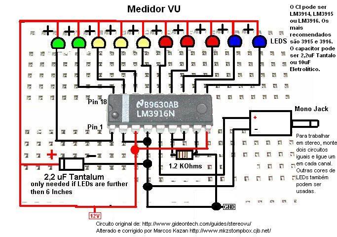
A post related to a do-it-yourself project for creating a VU meter and homemade rhythm lights that are easy to assemble. The project involves designing and constructing a visual audio level meter (VU meter) that responds to sound levels, as...
Typically, an LED is powered by a DC supply; however, this circuit enables the LED to be powered by an AC supply. This circuit can serve as a power indicator for a water pump. The circuit for powering an LED...
This Project is made up with AT89C2051 and the RTC DS1307. It has a large Seven segment display. The standard remote control is used to change the Time. More: Procedure to enter the Time 1. Press power button on...
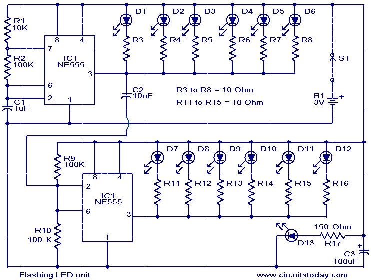
The circuit presented is designed as an LED flasher that creates a rotating effect when the LEDs are arranged appropriately. It operates with very low current consumption and can function using 3V button cells. The first integrated circuit (IC1),...
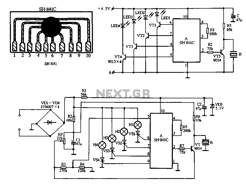
Figure 2-78 illustrates the SH-841 as the central component in a holiday lights controller. It utilizes SCRs VS1 to VS4 to drive light strings H1 to H4, causing them to flash. The operating voltage is sourced from AC through...
Warning: include(partials/cookie-banner.php): Failed to open stream: Permission denied in /var/www/html/nextgr/view-circuit.php on line 713
Warning: include(): Failed opening 'partials/cookie-banner.php' for inclusion (include_path='.:/usr/share/php') in /var/www/html/nextgr/view-circuit.php on line 713