
Switch Timer For Bathroom Light
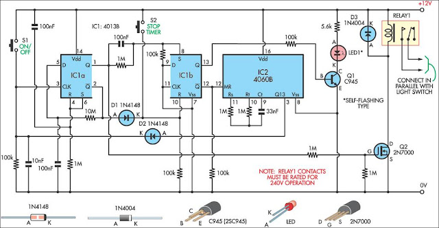
The described timer switch circuit employs a 4013 dual flip-flop integrated circuit (IC1) to manage the timing and control of a relay that operates a light fixture. The operation begins when the user presses switch S1, which toggles the state of flip-flop IC1a. This action energizes the relay through the field-effect transistor (FET) Q2, allowing current to flow to the light fixture. If the user does not deactivate the switch within nine minutes, the timer automatically turns off the light to conserve energy.
For continuous operation, the user must press S1 to turn on the light and then press S2 within the nine-minute timeframe to cancel the timer function. This allows the light to remain on indefinitely until S1 is pressed again to turn it off. The dual flip-flop configuration of IC1 allows for a simple yet effective state management system, where IC1b, configured as an RS flip-flop, can enable or disable the oscillator IC2, which is a 4060 model.
The 4060 IC serves as an oscillator and frequency divider, with its timing characteristics determined by external components connected to pins 9, 10, and 11. These components typically include resistors and capacitors that set the desired timing interval. The relay utilized in this circuit must have contacts rated for at least 250VAC to safely handle the mains voltage, and it is connected in parallel with an existing wall switch, allowing for seamless integration into the existing electrical system without requiring extensive modifications. This design provides a practical solution for managing lighting in spaces such as bathrooms or toilets, enhancing convenience and energy efficiency.This 9-minute timer switch can be used to control the light in a toilet or bathroom. The timer is started by pushing S1 and stopped by pushing S1 again. If you forget to turn it off, the controlled light will go off after nine minutes. If you need the light on continuously non-stop, you need to press S1 (turn on) and then S2 (cancellation of timer ) within 9 minutes and in this case the light will be on until you switch it off with S1. IC1 is a is 4013 dual flip-flop. Flip flop IC1a is toggled on and off by switch S1 and it controls the relay which is switched by FET Q2. IC1a controls IC1b which is connected as an RS flipflop to enable or disable IC2, a 4060 oscillator/divider.
This has its timing interval set by the components at its pins 9, 10 & 11. The relay should have 250VAC mains-rated contacts and these are connected in parallel with an existing wall switch. 🔗 External reference
Related Circuits
Currently, batteries are becoming increasingly powerful, serving as the sole energy source for portable electronic devices. The rapid evolution of battery technology has prompted manufacturers of electronic equipment to strive for reduced power consumption in their products, enabling them...
This sound-activated switch allows for control through sound, which can be beneficial not only in robotics but also in home automation applications. The sound-activated switch operates by detecting specific sound frequencies or patterns, typically using a microphone or a sound...
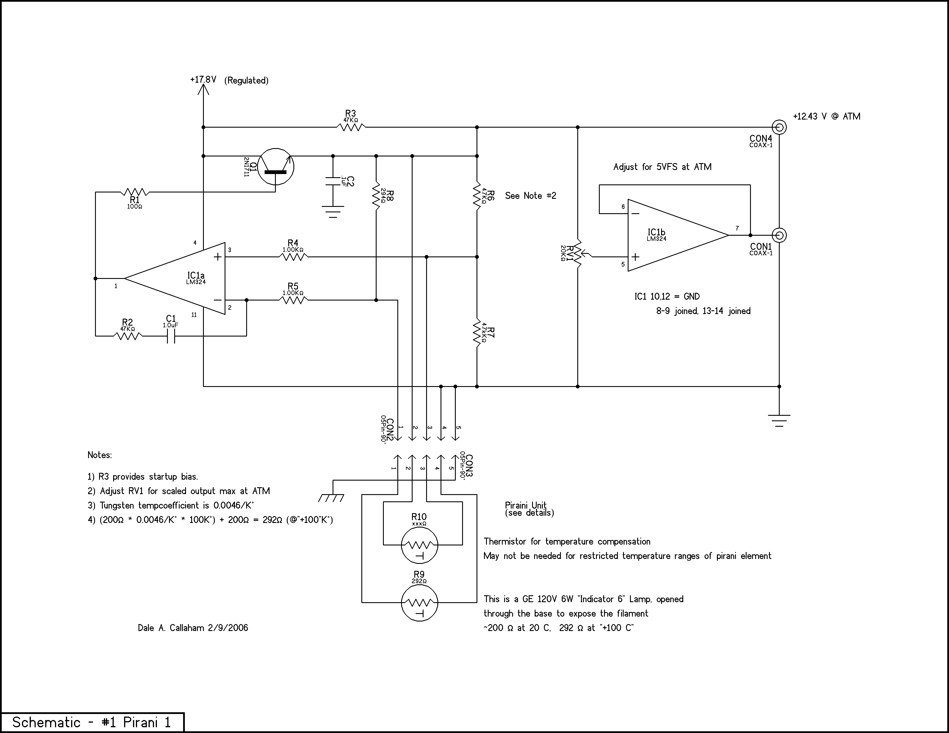
The principle is that the resistance of metals increases at higher temperatures, and a heated wire suspended in a gas will lose heat by conduction and convection in proportion to the number of gas molecules present; thus, the heat...
A video switcher circuit is required to display multiple sources on a single monitor. The circuit schematic below features the MAX454, which serves as the core component of this video switcher. The MAX454 is a video multiplexer-amplifier manufactured by...
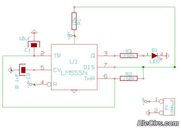
This is a very simple 555 timer circuit that serves as a straightforward theft deterrent, which may be just as effective. The idea is to have a flashing red LED indicate that your car is protected. This device can...
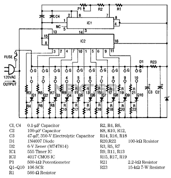
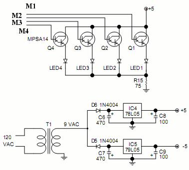
The light sequencer employs two integrated circuits (ICs) and ten silicon-controlled rectifiers (SCRs) to create an alternating current (AC) sequencer. The first IC, a 555 timer, is configured as an astable multivibrator to generate clock pulses for the second...