
Light control circuit diagram
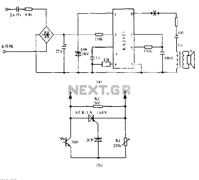
The described circuit effectively integrates a telephone ringing signal with a light control mechanism, employing the KA2401 as the core component. The KA2401 is a specific integrated circuit designed to generate ringing signals for telecommunication applications. It provides dual output signals that can be utilized to trigger other electronic components within the circuit.
The operation of the light control circuit hinges on the behavior of the photodiode (3DU). During the day, when ambient light levels are high, the photodiode exhibits low resistance, allowing for sufficient current flow to activate the thyristor (SCR). This activation results in a pronounced ringing sound, suitable for daytime conditions when background noise may mask quieter signals.
In contrast, the circuit is designed to adapt to nighttime conditions. As the light diminishes, the resistance of the photodiode increases significantly, which alters the functioning of the circuit. The higher resistance limits the current that can flow through the thyristor, thereby reducing the overall ringing signal. This is further influenced by the presence of resistor R2, which acts to attenuate the ringing signal even more, ensuring that it remains subtle and less intrusive during nighttime hours.
The implementation of this circuit is advantageous in environments where it is necessary to manage sound levels based on the time of day, providing a practical solution for residential or commercial applications. The use of the KA2401 in conjunction with the photodiode and thyristor creates a responsive system that balances functionality with user comfort.Use of ordinary telephone ringing circuit KA2401 and peripheral components, the installation of the light control when the bell simply access in the country (a) the "X" at the country (b), the light control circuit can be: external AC when the ringing signal input, KA2401 two 8-pin output signal ringing tone, if during the day, photodiodes 3DU resistance is small, the thyristor SCR turns on, ringing larger; if no light at night, 3DU resistance is (number Meg), only through the ringing signal attenuation by R2, ringing much smaller.
Related Circuits
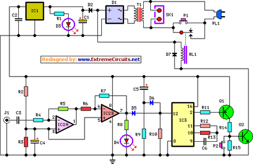
This circuit deactivates an amplifier or any connected device when a low-level audio signal is absent at its input for at least 15 minutes. Activating switch P1 powers the device, enabling operation of any appliance connected to SK1. The...
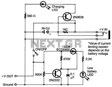
Intended for a NiCad application, this charging circuit can be used with a wide range of batteries. A low-battery detector is included, and the trip voltage is set via a 500 kΩ potentiometer. Select the resistor for the battery...
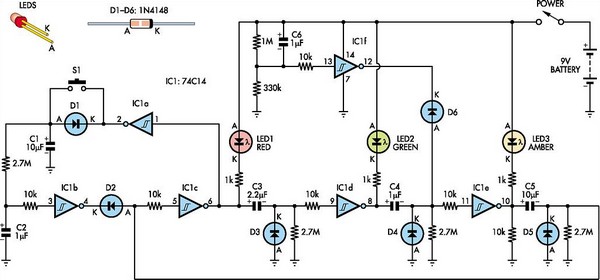
This toy traffic signal utilizes a single, cost-effective hex Schmitt-trigger inverter IC (IC1a-IC1f) to directly control three colored LEDs (red, green, and amber). Upon activation, the circuit illuminates the red signal for 30 seconds, followed by the green signal...
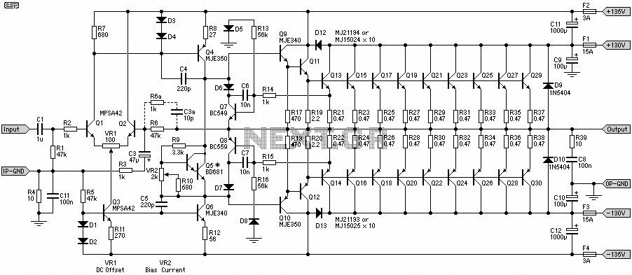
This 1500W Power Amplifier Circuit Diagram contains two images of the circuit. For more complete information, refer to the main post titled "1500 Watt Power Amplifier." It includes a list of component parts for the 1500W Power Amplifier Circuit...
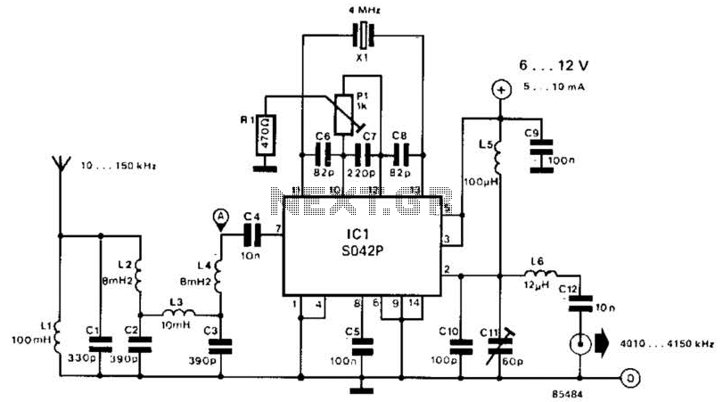
This converter shifts frequencies from 10 kHz to 150 kHz up to 4.01 to 4.15 MHz, suitable for use with a shortwave receiver for very low frequency (VLF) reception. A 4 MHz local oscillator frequency is utilized, and the...
This is the large controller utilized for the game Steel Battalion for the Xbox. The schematic diagram was sourced from an individual named Alpha who created it for his own use. The Steel Battalion controller is a specialized input device...