
Linear power supply circuit
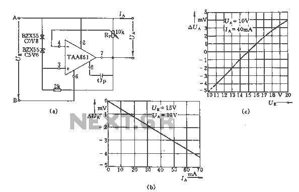
The regulator circuit described utilizes a potentiometer (Rp) to finely adjust the output voltage (Ua) within a specific range, providing flexibility in applications requiring variable voltage levels. The circuit's linear regulation characteristics ensure that the output voltage changes proportionately with variations in load current (Ia), which can reach up to 70 mA.
The input voltage (Ue) is designed to operate between 11 V and 20 V, allowing for compatibility with various power supply configurations. The output voltage (Ua) can be set between 8 V and 18 V, accommodating different load requirements. This range ensures that the circuit can effectively power devices with varying voltage needs.
The circuit's performance is characterized by its voltage regulation capabilities, particularly noted at specific conditions: when the input voltage is at 1 V and 15 V, the output voltage stabilizes at 10 V with a load current of 40 mA. This indicates that the circuit can maintain a consistent output despite fluctuations in input voltage, which is crucial for sensitive electronic applications.
Load regulation is also a significant feature, where the circuit maintains stable output voltage (Ua = 10 V) across a load current range of 0 to 60 mA when the input voltage is fixed at 15 V. This demonstrates the circuit's ability to adapt to varying load conditions without significant deviations in output voltage.
The dynamic resistance of the circuit, measured at 60 mΩ, indicates minimal voltage drop across the regulator during operation, contributing to efficient power delivery. Furthermore, the temperature coefficient of the output voltage, ranging from 3 to 5 x 10^-5 V/K, suggests that the output voltage will experience only slight variations with changes in temperature, enhancing the reliability of the circuit in diverse environmental conditions.
Overall, this regulator circuit is suitable for applications requiring precise voltage control and stability, making it a valuable component in various electronic systems.By the regulator circuit output voltage of the potentiometer Rp, and has a linear regulation characteristics. Figure (b) shows the output voltage Ua deviation with the load current Ia (0-70mA) a curve of FIG. (C) for the same input voltage Ue of the curve. Main technical data: Input voltage: Ue = 11 ~ 20V Output voltage: Ua = 8 ~ 18V Maximum output current: Ia = 70mA Voltage Regulation (Ue = 1V, Ue = 15V, Ua = 10V, Ia = 40mA); Load regulation (Ia = 0 ~ 60mA, Ue = 15V, Ua = 10V); Dynamic resistance: R1 = 60m Euro Temperature coefficient of the output voltage: 3 ~ 5X10⁻⁵ V / K
Related Circuits
The circuit should default to the "on" state when first connected. However, if a specific signal goes high for a brief duration (approximately 10 microseconds), the circuit should turn off and remain off. The challenge lies in achieving the...
Is there a circuit that can be used to make a DC motor move randomly backward and forward, stop for a period, and then start again? Any assistance and ideas would be greatly appreciated. Research how to wire up...
This gated 1-kHz oscillator provides press-to-turn-off functionality, along with waveforms available at the output of pin 3 and across capacitor C1. The gated 1-kHz oscillator circuit is designed to generate a square wave output at a frequency of 1 kHz....
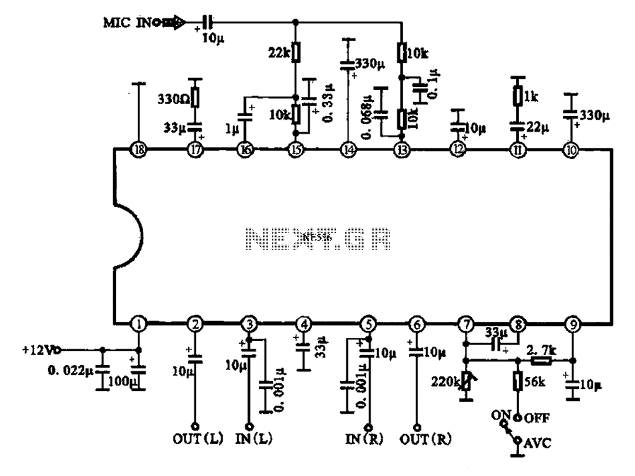
Automatic volume adjustment with ambient noise control circuit. In car stereos and similar devices, the ambient noise level varies during high-speed and low-speed driving or while stationary, leading to different volume requirements. A fixed volume adjustment method may negatively...
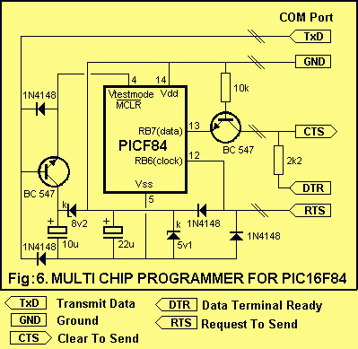
This project is designed to program the 8-pin PIC12c508A and 18-pin PIC16F84 microcontroller chips to support the projects we have designed; however, it will also program a number of other 8-pin and 18-pin microcontrollers, and the full list can...
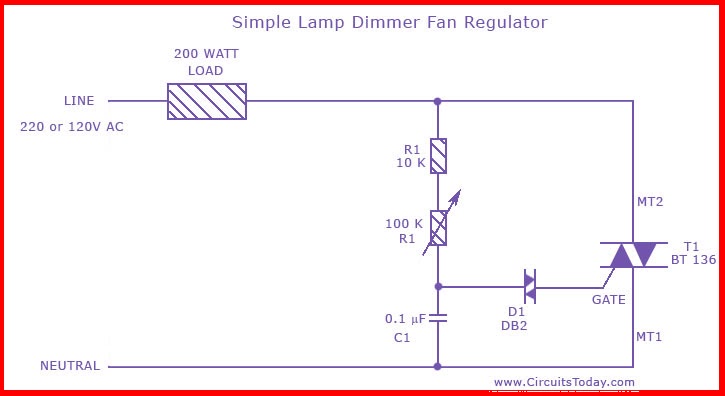
This is the circuit diagram of the simplest lamp dimmer or fan regulator. The circuit is based on the principle of power control using a Triac. The circuit operates by varying the firing angle of the Triac, which is...
Warning: include(partials/cookie-banner.php): Failed to open stream: Permission denied in /var/www/html/nextgr/view-circuit.php on line 713
Warning: include(): Failed opening 'partials/cookie-banner.php' for inclusion (include_path='.:/usr/share/php') in /var/www/html/nextgr/view-circuit.php on line 713