
Lite + Xtall RX V9.0 Schematic
The RX + Xtall V9.0 SDR schematic is a sophisticated representation of a software-defined radio receiver that employs advanced signal processing techniques to enhance user experience and operational flexibility. The design emphasizes modularity, allowing for easy upgrades and modifications through the use of interchangeable components such as the bandpass filters. The programmable local oscillator (U4) plays a critical role in defining the center frequency, which is essential for the effective operation of the SDR. By generating a frequency that is four times the desired center frequency, the design ensures that the signals are properly down-converted to the audio frequency range.
The implementation of the divider chain (U6) is crucial for maintaining the phase relationship between the I and Q signals. This phase relationship is fundamental for accurate demodulation and processing of the received RF signals. The mixer stage (U7) is designed to efficiently combine the RF input with the local oscillator signals, producing the desired quadrature outputs that facilitate further processing.
The integration of the USB control circuit (U2) allows seamless communication between the SDR hardware and the PC software, enabling real-time frequency adjustments and signal processing capabilities. This integration is essential for modern SDR applications, where user interaction and control are paramount.
Overall, the RX + Xtall V9.0 SDR schematic exemplifies the principles of modern SDR technology, showcasing a blend of hardware and software that allows for enhanced performance and flexibility in the reception and processing of radio signals.Below is the main schematic of the RX + Xtall V9. 0 SDR. The schematic has been partitioned into separate stages, each of which is covered in a separate page of build instructions in this web site. You can click on each shaded area and view the corresponding stage builders` notes. This receiver is patterned on the classic "direct conversion" receiv er, in that it mixes incoming RF down to audio frequencies by beating the RF against a Local oscillator such that the mixer products are in the audio frequency range. Unlike the traditional DC receiver, the SDR does not "tune" the local oscillator`s frequency to beat up against a desired RF signal.
Instead, the local oscillator generates a fixed, "center frequency. The beauty of an SDR design is that the operator can, in one display, "see" all activity within the design bandwidth and immediately "click" on any interesting signal within that spectrum. This version (9. 0) of the Softrock SDR receiver has a programmable local oscillator (U4 in the schematic below), permitting the operator to select any desired center frequency.
Frequency selection is done in a SDR program on the PC, and implemented via a USB connection and control circuit (U2 in the schematic below). The local oscillator is the Silabs Si570, of which there are two versions: LVDS - which requires U5, a high-speed, differential receiver that translates LVDS levels, with a typical differential input threshold of 100 mV, to LVTTL signal levels While it would be tempting to use that frequency progammability to directly tune the oscillator to a specific desired frequency, the SDR design for Version 9.
0 follows the SDR paradigm of providing a "chunk" of spectrum that is simultaneously detected and presented for processing in the PC. To accomplish this, the SDR hardware must present the "chunk" of spectrum as two down-converted chunks of AF in quadrature, the "I (in-phase) and the "Q" (quadrature) outputs.
Most SDR designs use the concept of a center frequency, on either side of which are arrayed the "chunk" of received frequencies in a "chunk" of the RF spectrum. For any desired center frequency, the oscilllator (U4 - red shaded area below) generates a frequency equal to 4 times the desired center frequency.
This signal is fed to a divider chain (U6 - blue shaded area below) that divides the input by 4 (with attendant phase shifts to achieve quadrature). The divider chain then outputs two signals at the desired center frequency and one-fourth of the input frequency.
These two center frequency signals are in quadrature - each identical, differing only in phase by 90 degrees. The two center frequency signals are passed to the mixer stage (U7 - green shaded area below), where they are mixed with and beat against the RF input from the band pass filter stage (BPF Module, blue-green shaded area below), resulting in two down-converted products that are quadrature AF analogues of the incoming RF signals.
As a result, the mixer products can vary in audio frequency from zero to +/- some theoretically high audio frequency. (Note: the pluggable bandpass filters may be replaced by the new switchable HF BPF board, which implements 4 switchable BPFs on a single board, which can be manually switched or (once firmware is updated) switched via USB control.
) These AF signals are then amplified in an inverting operational amplifier (U8 - grey shaded area below) to produce the I and Q signals for consumption and digitization by the PC`s sound card. The "tuning", image rejection, demodulation, AFC and other neat radio functions happen in the software part of the Software Defined Radio.
It is the magic of Software that makes for the extraordinarily high selectivity in the direct conversion hardware (which is notorious for great sensitivity but terrible selectivity). The software allows the display of the audio frequency manifestations of the RF "chunk" on a display calibrated in the R
🔗 External reference
Related Circuits
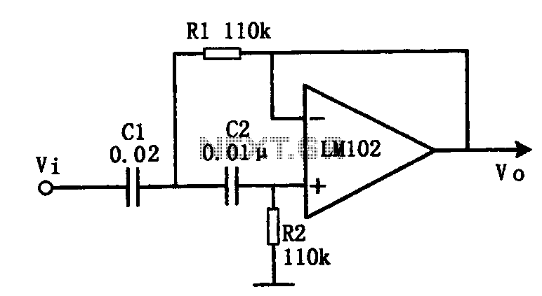
This document presents an active low-pass filter circuit with a cut-off frequency (fc) of 10 kHz. The circuit allows for various values for the ratios of resistors R1 and R2, as well as capacitors C1 and C2. Specifically, it...
Some simple 555 and flip-flop circuits are being developed to add electronic lighting effects to modernize games. Various circuits are being collected for different game aspects, such as idle states, flipper shots, flower openings, winning shots, etc. A collection...
In this circuit, a 74HC14 hex Schmitt trigger inverter is used as a square wave oscillator to drive a small signal transistor in a class C amplifier configuration. The oscillator frequency can be either fixed by a crystal or...

This is a simple and low-cost NiCd and NiMH battery charger. The schematic diagram indicates that the charging current (I) should be set to 1/10 of the battery's rated capacity. For instance, if the battery has a rated capacity...
This circuit utilizes two quad op-amps to create an eight LED audio level meter. The op-amp employed in this circuit is the LM324, a widely used integrated circuit that is readily available from numerous electronic component suppliers. The 1K...
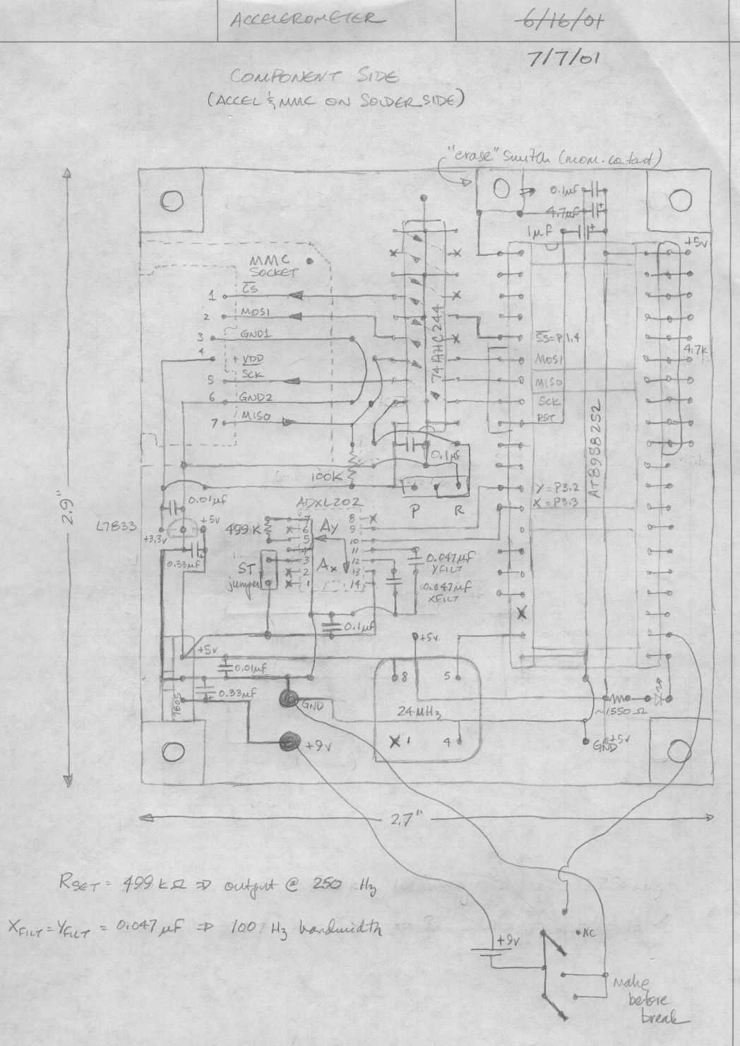
Below is a rough schematic of the layout of the accelerometer PC board looking from the component side. The microcontroller is an Atmel AT89S8252, an 8051 clone. This microcontroller is in-circuit programmable using an SPI interface. The SPI pins...