
lithium polymer peak charger

The charging circuit for Lithium-Polymer cells typically incorporates a dedicated charger IC, which is designed to manage the unique requirements of these batteries. A common charging method used is the constant current/constant voltage (CC/CV) approach. Initially, the charger supplies a constant current until the battery voltage reaches a predefined threshold, typically around 4.2 volts per cell. At this point, the charger transitions to constant voltage mode, maintaining the voltage while allowing the current to taper off as the battery approaches full charge.
In addition to the charging IC, the circuit may include a microcontroller for monitoring the charging process and ensuring safety features are in place. This microcontroller can manage temperature sensors to prevent overheating, as Lithium-Polymer cells are sensitive to temperature variations. Furthermore, the circuit design should incorporate a balance charging feature, especially if multiple cells are connected in series. This ensures that each cell receives the appropriate charge, preventing overcharging and extending the overall lifespan of the battery pack.
Protection circuitry is also critical in the design. This can include over-voltage, under-voltage, and over-current protection to safeguard the cells during both charging and discharging. Fuses or resettable polyfuses may be implemented to provide additional safety measures.
Overall, the design of a Lithium-Polymer charging circuit for model aircraft must prioritize weight reduction, efficiency, and safety, ensuring optimal performance while adhering to the strict charging requirements of Lithium-Polymer technology.This circuit was developed to charge the Lithium-Polymer cells used in a model aircraft. Lithium-Polymer cells are incredibly lightweight compared to Ni-cad battery packs of the same voltage and amp-hour rating. Their only drawback is that they require a rigid charge and discharge regime to achieve maximum life..
🔗 External reference
Related Circuits
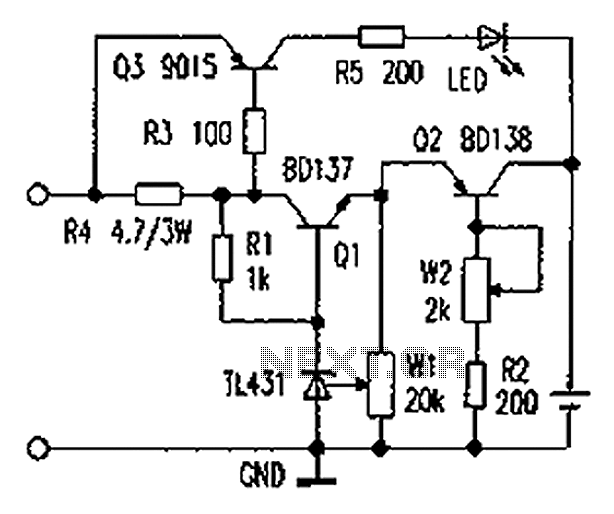
As illustrated in the figure, the lithium battery charging control board employs a constant current charging mechanism. The components Q1, R1, W1, and TL431 form a precision adjustable voltage regulator circuit. The components Q2, W2, and R2 create an...
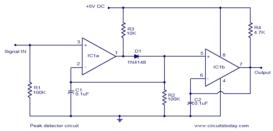
LM339-based peak detector circuit. Simple and easy to construct. Operates from a 5V DC single supply. LM339 is a dual comparator. The LM339-based peak detector circuit is designed to capture and hold the peak value of an input signal. This...
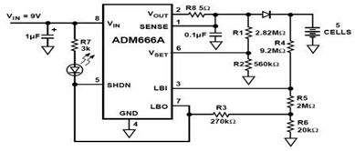
The ADM666A application note provides a detailed explanation of a low-cost battery charger circuit, including maximum output voltage, charge termination voltage calculation, battery voltage level monitoring, and circuit efficiency optimization. The ADM666A utilizes an NPN transistor and a P-channel...

This circuit provides a simple and efficient method to draw current from a motorcycle battery to charge a mobile phone. Most mobile phone battery packs consist of three 1.2-volt cells, resulting in a total voltage of 3.6 volts. For...
In today's world, owning a car battery charger at home has become essential. Having one readily available can help prevent starting issues caused by battery problems. While purchasing a commercial battery charger can be expensive, the components required for...
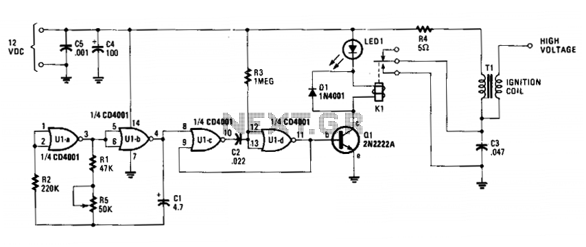
The circuit is fundamentally an auto ignition coil paired with a set of points that perform a similar function. It employs a pulsing circuit constructed from a single CMOS NOR integrated circuit (U1) to open and close relay contacts,...