
Load Sensing Automatic Switch
The mains current detector circuit utilizes a minimalistic design to achieve effective opto-isolation while detecting AC current. The primary components include low-cost diodes, a resistor, an LED, and a light-dependent resistor (LDR). The diodes are arranged to rectify the AC mains current, allowing the circuit to operate with minimal power dissipation.
The LED serves as an indicator, illuminating when current is detected, while the LDR is utilized to enhance the opto-isolation aspect of the circuit. The heatshrink wrapper serves a dual purpose: it protects the circuit from accidental contact with live wiring and shields the LDR from ambient light, ensuring accurate detection of current.
The circuit has been tested to detect currents as low as 10mA, demonstrating its sensitivity and effectiveness. At a load of 0.5A, the circuit operates without distress, although it is noted that the diodes may become warm under higher current conditions. It is crucial to adhere to the specifications of the components used; the current rating of the diodes is a critical factor, as the circuit is designed for a maximum switched load of 1A. For applications requiring higher current detection, the use of diodes rated for higher currents is strongly recommended to prevent component failure.
This circuit design exemplifies a practical solution for current detection in various applications, leveraging simple components for reliable operation while maintaining safety standards.The circuit of the mains current detector is shown in Figure 1. By using a few cheap diodes, a resistor, LED and LDR, a simple opto-isolated detector can be created. This entire circuit dissipates very low power, and can safely be housed in a heatshrink wrapper to ensure that contact with live wiring is not possible.
This will also keep light away from the LDR. These are cheap and easy to use. I found that I could detect as little as 10mA of mains current with this circuit, and no distress was created at 0.5A. The diodes will get very warm at higher currents. Note that because of the 1A diodes used, this is the absolute maximum current of the switched load. If a higher current is expected, you must use high current diodes to prevent failure. I shall leave it to the reader and the local electronics supplier t 🔗 External reference
Related Circuits
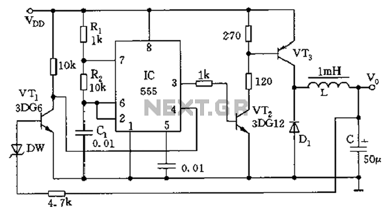
The circuit consists of a 555 timer configured as an astable multivibrator along with resistors R1 and R2 and capacitor C1. It generates an oscillation frequency of approximately 10 kHz with a duty cycle close to 50%. Transistors VT2...

This project involves an automatic room light controller with a bidirectional visitor counter using a microcontroller. It is designed to manage room lighting and accurately count the number of individuals present. When a person enters the room, the counter...
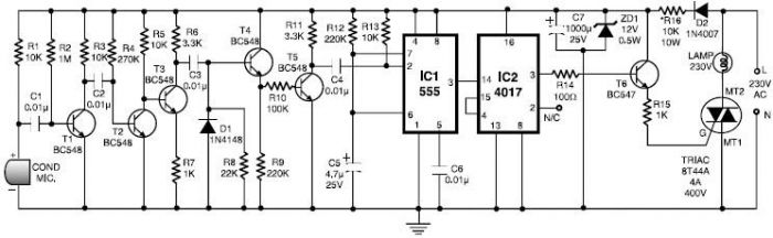
This 555 timer clap switch circuit electronic project is designed using common electronic components. The 555 timer clap switch circuit utilizes a 555 timer IC in a monostable configuration to create a sound-activated switch. The circuit is triggered by...
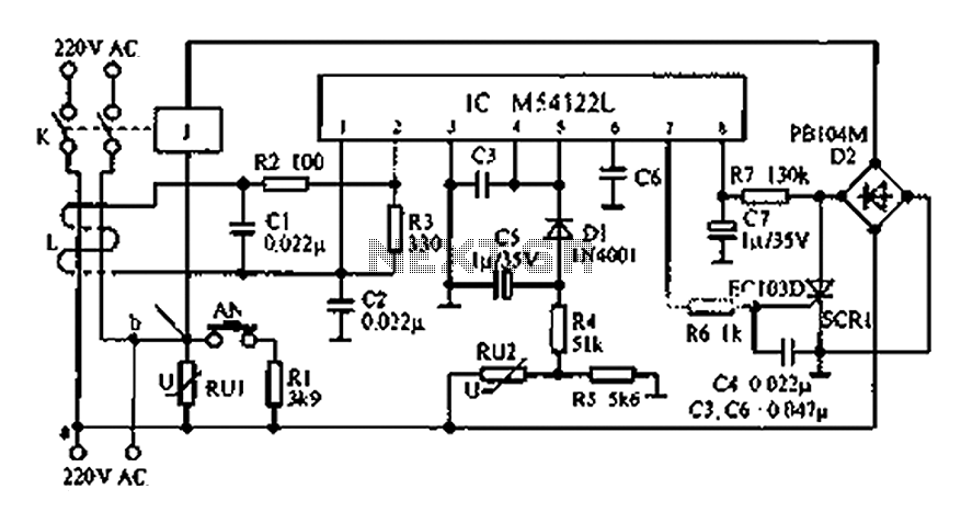
The multifunction leakage protection switch utilizes the Nissan ASIC M54122L. It is designed to serve as a multi-function leakage protection switch. In the event of leakage or electric shock, the magnetic field generated through the inductor line and neutral...
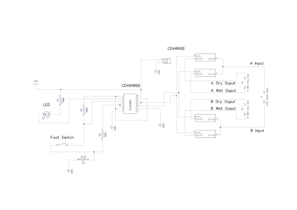
A simple audio switching circuit is experiencing issues. The circuit utilizes a CD40106 Schmitt Trigger in conjunction with a CD4066 CMOS switch to route audio signals. The circuit design incorporates a CD40106 Schmitt Trigger, which is essential for providing clean...
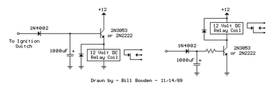
The two circuits illustrated show the operation of opening a relay contact shortly after the ignition or light switch is turned off. A capacitor is charged, and the relay remains closed until the voltage at the diode anode rises...