
Loudspeaker Protection 2

Part List
R1-2=27 Kohms R13=1.5 Kohms Q1-2-3=BC337
R3=1.4 Kohms R15=4.7 Kohms Q4=BC639
R4=1 Mohms R16=33 Kohms D1=1N4148
R5-14-17=3.3 Kohms R18=1.5 Kohms 5W D2=1N4004
R6-7=100 Kohms RTH=KTY81-122 D3=15V 1.5W Zener
R8=47 Kohms C1-2=100uF 63V D4=1N4002
R9-11=120 Kohms C3=470nF 100V MKT D5-6=LED
R10=470 Kohms C4-5=47uF 25V RL1=24V Relay
R12=15 Kohms IC1=LM393
This circuit is designed to ensure the protection of loudspeakers connected to a power amplifier by isolating them under specific conditions, such as excessive continuous voltage or overheating. The integration of a binary comparator allows for monitoring and decision-making based on voltage levels, while the use of transistors ensures swift response to protect the loudspeakers. The circuit also incorporates both voltage and thermal protection features, enhancing its reliability in various operational scenarios. The inclusion of time delay mechanisms prevents speaker damage from transient signals, contributing to the overall robustness of the system.The circuit protection output of power amplifiers and loudspeakers, dispose certain interesting elements, as the isolation of loudspeakers from the exit of amplifier, when is presented continuous voltage in his exit or when the temperature of heatsink, goes up excessively, providing simultaneously and time delay in the connection loudspeakers in the amplifier, so that we avoid pass in them, the known annoying noises from the charge - discharge of capacitors of supply. It?s constituted by a binary comparator [ IC1 ], the transistors Q1-2 and indicative LED D5-6. The supply of circuit can become from positive voltage [ Point A ] of mainly power supply, which is stabilised by the D3 and the R17, in + 15V.
Point B is connected in one of the secondary AC coil of main transformer. If close the main switch of main line AC, then a AC voltage (in secondary coil of transformer), is presented in the point B, it?s rectified from the D2 and it supply with negative voltage, via the R9, the Q3, this cut off and it begin charge the C4 via the R10-11. As long as time therefore last the charge of capacitor, the input [+] of comparator IC2B is found in low level concerning input [-].
The exit of IC2B, has low level, therefore the Q4 remain in cutt off and the RL1 remain deactivate, the D6 he is ON. Just the C4 charged, change the situation of IC1B, is activated the RL1, the loudspeaker are connected in the amplifier output, the D6 it OFF.
When it?s interrupted the supply, all the process is inverted, and the loudspeaker disconnect, without pass annoying noises. If as long as it work the circuit, is presented problem of continuous voltages in the exit of amplifier then turn off of RL1 and protected the loudspeakers.
This become with help the Q1-2. The acoustic signal from the exit of power amplifier, is led to point D, the alternate voltages is led to the ground via the C1-2, that create a not polar capacitor. Continuous voltages, bigger than + 1.7V or smaller than ?4.8V, activate immediately the Q1 or the Q2, respectively.
With the activation of transistors goes down the level of input [+] of IC1B, so that turn off and the RL1. A other section of protection that for us provide the circuit is the thermic protection. This become with the help of sensor temperature the RTH, which is a resistor of type PTC (positive factor of temperature), and is found placed above in heatsink, where are found also the power transistors.
Her price increase, with the increase of temperature, until the potential in input [-] of IC1A, goes up above from the level of input [+], which is determined with the voltage divider R2-3. As soon as the level in input [-] exceed the level of input [+], the exit of IC1A, it return in low level, compelling and the IC2B to change situation, turn off the RL1 and to turn on the D5, that show the thermic protection.
In the circuit the limit above which it exist clue of thermic protection they are 70?C. If it?s presented instability, in this stage, in operation of RL1, should be changed the R4, with other of smaller price. The circuit was published in magazine ?Elektor? 12/95. Part List R1-2=27 Kohms R13=1.5 Kohms Q1-2-3=BC337 R3=1.4 Kohms R15=4.7 Kohms Q4=BC639 R4=1 Mohms R16=33 Kohms D1=1N4148 R5-14-17=3.3 Kohms R18=1.5 Kohms 5W D2=1N4004 R6-7=100 Kohms RTH=KTY81-122 D3=15V 1.5W Zener R8=47 Kohms C1-2=100uF 63V D4=1N4002 R9-11=120 Kohms C3=470nF 100V MKT D5-6=LED R10=470 Kohms C4-5=47uF 25V RL1=24V Relay R12=15 Kohms IC1=LM393
🔗 External reference
Related Circuits
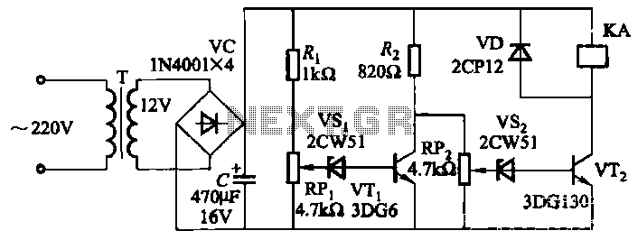
The circuit employs a transistor control mechanism. When the grid voltage is within the normal range, relay KA is activated, supplying power to the load. If the grid voltage falls below the minimum allowable threshold (adjustable via potentiometer RPz)...
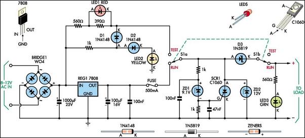
This 8V DC power supply is designed for use with high-end electronic equipment. It includes full over-voltage protection to safeguard against regulator failure, whether in the supply itself or in the connected device. The circuit employs a standard full-wave...
There are many circuits for low voltage regulators. For higher voltages, such as supplies for valve circuits, the situation is different. Low voltage regulators are widely utilized in electronic circuits to provide a stable output voltage from a varying input...
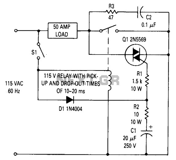
This circuit can be utilized to prevent relay contact arcing for loads up to 50 amperes. A delay exists between the moment a relay coil is energized and when the contacts close, as well as a delay from when...
The 5 volt regulated power supply for TTL and 74LS series integrated circuits has to be very precise and tolerant of voltage transients. These ICs are easily damaged by short voltage spikes. A fuse will blow when its current...
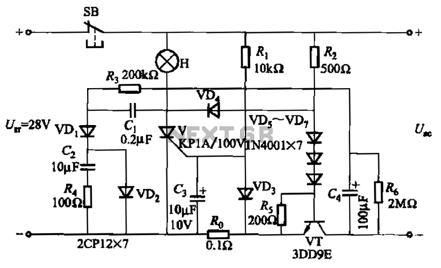
Capacitor C3 is used to determine the cutoff power, specifically the voltage threshold (VT cutoff), which influences the delay time selection. The schematic includes a reset button, SB, that is utilized to reset the system after a failure has...