
Mains undervoltage overvoltage protection circuit
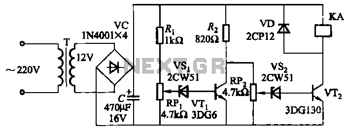
The described circuit functions as a protective relay system designed to monitor and control power supply to a load based on grid voltage levels. The core component of this circuit is a transistor, which serves as a switch that controls the operation of relay KA.
In normal operation, when the grid voltage is stable and within the predefined limits, the transistor is biased appropriately, allowing current to flow through its collector-emitter path. This action energizes relay KA, which closes its contacts and connects the load to the power supply.
The circuit includes two adjustable resistors: RPz and RPi. RPz is used to set the minimum allowable voltage threshold, while RPi establishes the maximum allowable voltage threshold. These thresholds can be fine-tuned according to the specific requirements of the application.
When the grid voltage drops below the set minimum (as determined by RPz), or rises above the set maximum (as determined by RPi), the transistor's biasing conditions change, causing it to turn off. This action deactivates relay KA, opening its contacts and cutting off power to the load to prevent damage from overvoltage or undervoltage conditions.
The implementation of this circuit enhances the reliability and safety of electrical systems by ensuring that loads are only powered when grid voltage is within acceptable limits. Additionally, the use of a potentiometer allows for easy adjustments to the threshold values, providing flexibility in various applications.It uses a transistor control circuit. When the grid voltage is normal, relay KA pull, turn the power load. When the grid voltage is below the minimum allowable value (can be set by the potentiometer RPz), or higher than the maximum allowable value (by RPi setting), KA is released, the load can be cut off the power supply.
Related Circuits

This small device can be aimed at a television to jam the remote control signal. The circuit design is straightforward. A 555 timer is configured as an astable multivibrator operating at a frequency of approximately 38 kHz, which is...
This timer was designed primarily to switch off a portable radio after a set period. This feature allows users to fall asleep on the beach or in a hammock, knowing that the receiver will automatically turn off after a...

This design outlines a door alarm circuit that utilizes an electronic system. It features a synthesized sound chip from Holtek, specifically the HT-2811, which reproduces the sound of a "ding-dong" chiming doorbell. The circuit also incorporates a CMOS 4026...
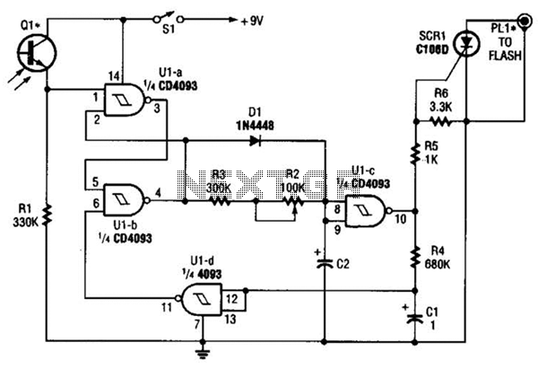
The circuit is built around a single 4093 quad 2-input NAND Schmitt trigger. Two gates from that quad package (U1-a and U1-b) are configured as a set-reset flip-flop. The 4093 integrated circuit (IC) contains four independent 2-input NAND gates with...
LED brightness control circuit: A simple circuit can be used to control the brightness level of an LED display. The LED brightness control circuit is designed to adjust the illumination level of an LED display according to user preferences or...
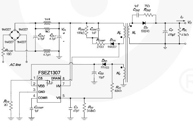
This cell phone charger circuit diagram electronic project is based on the FSEZ1307 third-generation primary side regulation (PSR) PWM controller integrated circuit. The FSEZ1307 cell phone charger can be used for battery charger applications for devices such as cellular...