
Low Power FM Transmitter

The transmitter circuit described is a straightforward design primarily focused on frequency generation through an oscillator. The oscillator is the first stage, which utilizes a variable capacitor (C3) for tuning. This capacitor allows the user to select a specific frequency by adjusting its capacitance. The process involves selecting an unused frequency and fine-tuning the capacitor until the background noise ceases, which is crucial for effective operation. It is important to disable the mute function of the FM receiver during this adjustment to clearly hear the changes in noise levels.
To ensure stable operation during tuning, it is critical that the rotor of the variable capacitor (C3) is connected to a +9V power supply. This connection minimizes frequency fluctuations that may occur when handling the tuning mechanism, such as when a screwdriver is used for adjustments. A practical tip for making adjustments is to use a non copper-clad circuit board piece as a screwdriver, as this material will not influence the frequency being generated.
Additionally, to enhance frequency stability, a capacitor should be connected from the base of transistor Q1 to ground. This configuration promotes the operation of the transistor in a true common base mode at radio frequencies (RF), which significantly improves the circuit's overall performance and reliability. The careful assembly and tuning of this transmitter circuit will lead to efficient frequency generation suitable for various applications in RF communication.The circuit of the transmitter is shown in Figure 1, and as you can see it is quite simple. The first stage is the oscillator, and is tuned with the variable capacitor. Select an unused frequency, and carefully adjust C3 until the background noise stops (you have to disable the FM receiver`s mute circuit to hear this). Because the trimmer cap is very sensitive, make the final frequency adjustment on the receiver. When assembling the circuit, make sure the rotor of C3 is connected to the +9V supply. This ensures that there will be minimal frequency disturbance when the screwdriver touches the adjustment shaft.
You can use a small piece of non copper-clad circuit board to make a screwdriver - this will not alter the frequency. The frequency stability is improved considerably by adding a capacitor from the base of Q1 to ground.
This ensures that the transistor operates in true common base at RF. 🔗 External reference
Related Circuits
Increasing the quiescent current (Iq) will result in more power output at 4 ohms. It is understood that decreasing the supply voltage affects performance. Increasing the quiescent current (Iq) in a circuit can lead to enhanced power output, particularly when...
The circuit is a standard RC phase shift oscillator that utilizes a single bipolar transistor as the active component. When power is supplied, regenerative feedback is applied through capacitor C2 from the collector to the base of the transistor....
This circuit is a basic design that includes indicator LEDs and appropriate resistor values. A dotted line indicates that the IR LED is connected to the circuit via a length of wire (in this case, a telephone cable). The...
This is a low-cost universal battery charger circuit. This circuit is designed to charge NiCd and NiMH batteries and is ideal for use in vehicles. The circuit converts mains voltage. The low-cost universal battery charger circuit is engineered to efficiently...
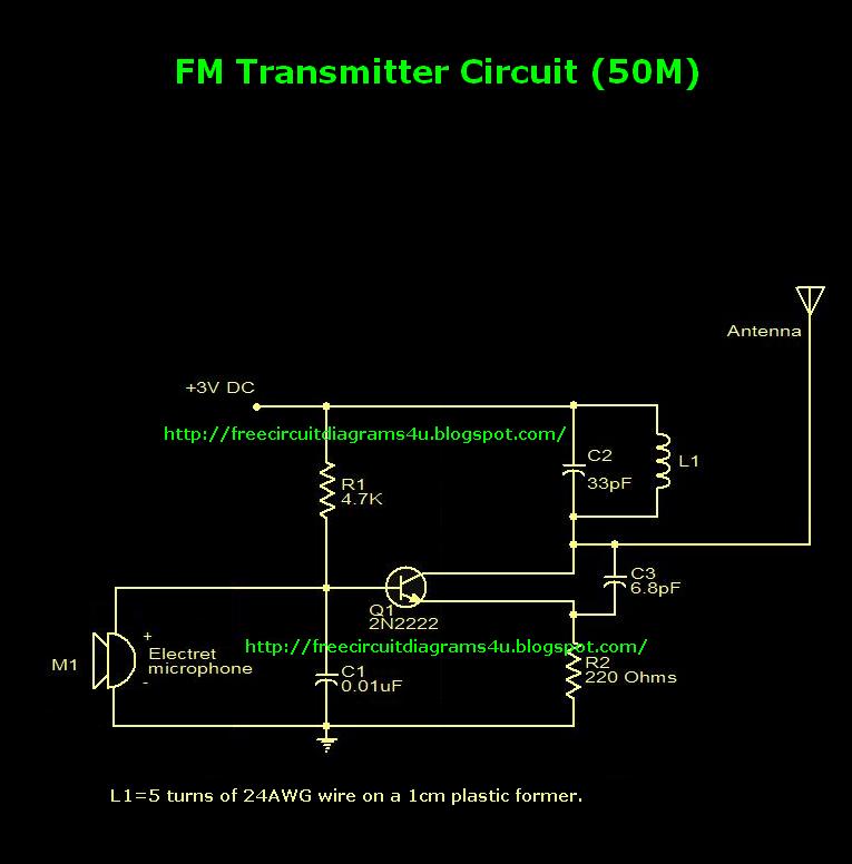
This is an FM transmitter circuit diagram. This circuit uses a 2N2222 transistor, allowing it to operate at 3V and transmit signals up to 50 meters. The FM transmitter circuit consists of several key components, primarily centered around the 2N2222...
Before starting on the receiver side of the Chatterbox, a final review of the transmitter is necessary. The Chatterbox transmitter is constructed separately, as many builders may wish to use it alongside an existing receiver operating at 1.8 MHz....