
Low voltage regulators
The described circuit employs a series of components to regulate voltage effectively while ensuring protection against potential faults. The primary elements include power transistors, zener diodes, resistors, and a heatsink for thermal management. The configuration allows for dual functionality, accommodating both positive and negative ground systems, which is critical for versatility in automotive applications.
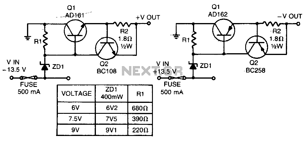
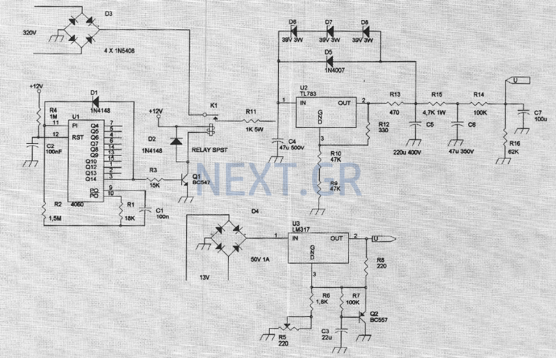
The voltage regulation is achieved through the use of a zener diode, which sets the reference voltage for the circuit. Resistor R1 is selected based on the desired zener voltage, ensuring that the output remains stable at either 6, 7, or 9 V, depending on the specific application requirements. The current flowing through the circuit is monitored, and under normal conditions, the voltage across R2 is maintained below the threshold that would trigger the activation of Q2.
In scenarios where the load demands exceed the circuit's capacity, Q2 acts as a protective switch. When the voltage across R2 rises above 500 mV, indicating an overload condition, Q2 conducts, effectively shutting off Q1. This mechanism protects the regulating transistor from damage due to excessive current, ensuring the longevity and reliability of the circuit.
Furthermore, the design's integration of power transistors directly onto the heatsink without insulating spacers not only simplifies assembly but also improves thermal dissipation. This feature is particularly advantageous in automotive environments where component temperatures can fluctuate significantly. Overall, the circuit exemplifies a robust solution for voltage regulation in automotive applications, combining efficiency, safety, and adaptability.These short-circuit protected regulators give 6, 7, and 9 V from an automobile battery supply of 13 V nominal; however, they will function just as well if connected to a smoothed dc output from a transformer/rectifier circuit. Two types are shown for both positive and negative ground systems. The power transistors can be mounted on the heatsink without a mica insulating spacer thus allowing for greater cooling efficiency.
Both circuits are protected against overload or short-circuits. The current cannot exceed 330 mA Under normal operating conditions the voltage across R2 does not rise above the 500 mV necessary to turn Q2 on and the circuit behaves as if there was only Q1 present. If excessive current is drawn, Q2 turns on and cuts off Ql, protecting the regulating transistor. The table gives the values of Rl for different zener voltages. 🔗 External reference
Related Circuits
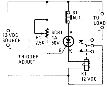
A silicon-controlled rectifier (SCR) is connected in parallel with the 12-V line and linked to a normally-closed 12-V relay, designated as K1. The gate circuit of the SCR is utilized to monitor the applied voltage. While the applied voltage...
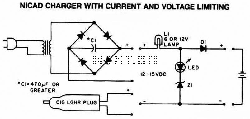
The following diagram is the schematic of a Ni-CAD battery charger circuit, which includes current and voltage limiting features to extend the battery's lifespan. The lamp L1 will illuminate brightly, and the LED will be off when the battery...
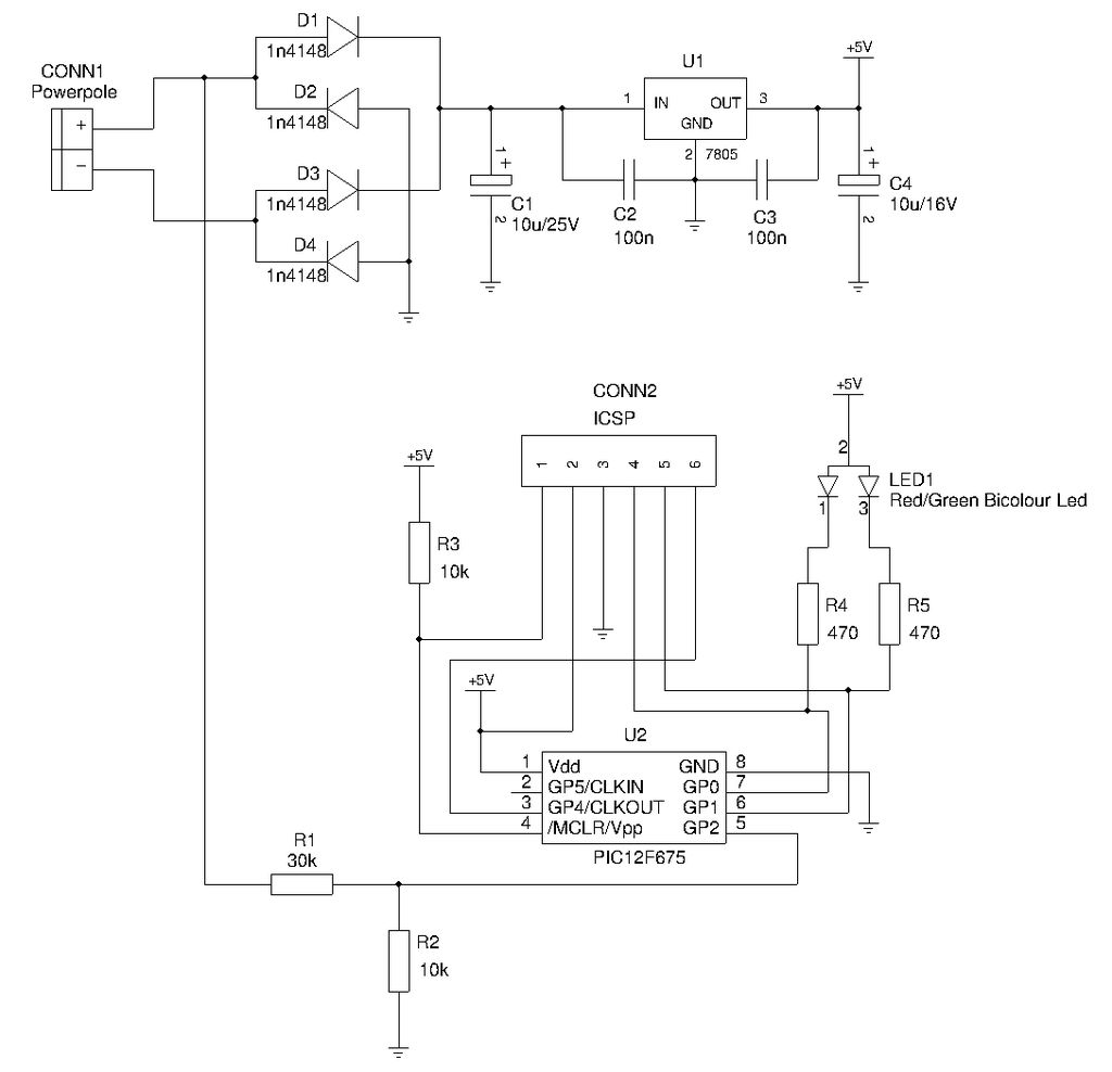
This is a compact device designed for amateur radio (HAM) enthusiasts, utilizing Powerpole connectors to interface HAM equipment with an unidentified power supply that also features Powerpole connectors. The device functions as an essential accessory for HAM radio operators,...
The drawback of the circuit mentioned is that the operational amplifier (op-amp) supply is connected to the high voltage (HV) supply. Most op-amps are limited to approximately 30V for their supply voltage, which prevents the circuit from functioning with...
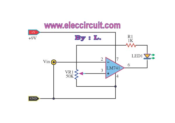
This simple low voltage tester circuit can be used to monitor batteries and other voltage sources for issues, utilizing an LED display and alarm sound. The low voltage tester circuit is designed to provide a reliable method for monitoring the...
The amplifier feeding the final amplification stage operates with unstabilized voltage. The output stage, utilizing push-pull operation, exhibits significant rejection of the supply voltage. However, the earlier stages do not provide the same level of rejection, resulting in unwanted...