
Mains Remote-Alerts
The circuit operates efficiently by utilizing the mains supply as a medium for signal transmission, eliminating the need for complex wiring or radio frequency components. The Darlington pair configuration of Q1 and Q2 provides high current gain, which is crucial for amplifying the signal generated by the Hartley oscillator. The oscillator's frequency of 135 kHz is significant as it is well within the range capable of being transmitted through standard electrical wiring without interference.
The rectification process involving diodes D1 and D2 ensures that the alternating current (AC) from the mains is converted into direct current (DC), which is necessary for powering the circuit components. The Zener diode D3 plays a vital role in voltage regulation, ensuring that the voltage supplied to the circuit remains stable at 30 Vdc, which is essential for consistent operation.
The tuning circuit consisting of L1 and C3 is critical for filtering the desired 135 kHz frequency from the mains. Proper tuning ensures that the circuit operates efficiently, with minimal loss of signal strength. The use of capacitors C3 with values ranging from 1 to 3.3 nF allows for flexibility in tuning, accommodating variations in component specifications.
The output stage, driven by Q2, is responsible for activating the load, which can be either a sound-producing beeper or a visual indicator such as an LED. The design allows for customization based on user preference, and the adjustment of resistor R7 when using an LED ensures optimal brightness, enhancing the visual alerting capability of the system.
Overall, this circuit design exemplifies an innovative approach to wireless signaling using existing electrical infrastructure, providing a practical solution for alert systems in residential settings.Pressing the pushbutton of the transmitter, a sound and/or light alert is activated in the receiver. The system uses no wiring or radio frequencies: the transmitted signal is conveyed into the mains supply line. It can be used at home, in any room from attic to cellar, simply plugging transmitter and receiver in the wall mains sockets.
Transmission range can be very good, provided both units are connected to the mains supply within the control of the same light-meter. Q1 and Q2 are wired as a Darlington pair to obtain the highest possible output from a Hartley type oscillator running at about 135KHz frequency. The 220Vac mains is reduced to 30Vdc without the use of a transformer by means of C1 reactance, a two diode rectifier cell D1 & D2 and Zener diode D3.
The 135KHz sinewave generated by the transmitter is picked-up from mains wiring by C1 and selected by the tuned circuit L1-C3. Q1 greatly amplifies the incoming sinewave and converts it in a 12V-peak squarewave. D4 & D5 limit the input voltage at Q1 base to less than 1V-peak to avoid damaging of the transistor due to the high voltage transients frequently occurring on the mains line.
D6 eliminates any negative component of the signal and Q2 drives the load. C7 is necessary to smooth the signal residues appearing across the load. The tuning of the coils at 135KHz frequency should be obtained with the ferrite core almost totally inserted in its slot, if 455KHz IF transformers are used for both L1s. Using IF transformers different from those specified, a change in both C3s value can be needed. The value of these capacitors may be varied from 1 to 3. 3nF but must be the same in transmitter and receiver. The load can be a beeper, a LED or both. Omitting the beeper and choosing the LED as the only load, its limiting resistor R7 should be reduced in value to about 1K, to increase device brightness.
In this case, a 10mm. diameter LED type or greater, can also be useful. 🔗 External reference
Related Circuits
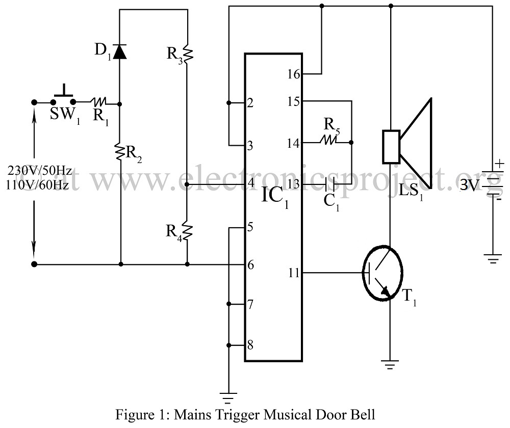
Mains-triggered musical doorbell using the musical IC UM3482 circuit diagram, featuring various and unique doorbell projects. The mains-triggered musical doorbell circuit utilizes the UM3482 integrated circuit, which is specifically designed for generating musical tones. This circuit is activated by a...
This circuit was designed to produce an audible alarm when the mains power is interrupted. Such an alarm is essential for anyone whose livelihood depends on continuous power supply. The circuit functions by monitoring the presence of mains voltage. It...
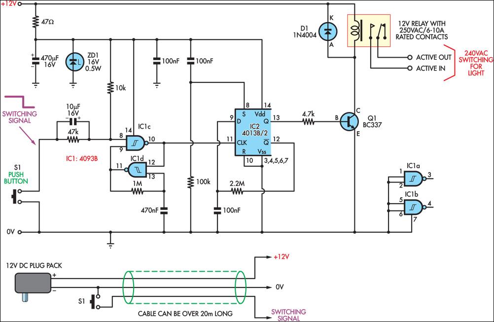
This circuit enables the remote control of a 240V mains appliance, such as a light bulb, through low-voltage cabling and a pushbutton switch. The mains appliance is activated using a suitably-rated relay. All electronic components are housed in an...

An array of white LEDs can serve as a small lamp for the living room. LED lamps are readily available, resembling standard halogen lamps, and can be installed in a standard 230-V light fixture. A capacitor is employed to...
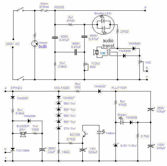
With this circuit you will be able to monitor the quality of the mains. There are 4 distinct sections, each supervising a parameter pertinent to the quality of the supply line. The noise section consists of a 50Hz filter...
The circuit below illustrates powering a LED (or two) from the 120 volt AC line using a capacitor to drop the voltage and a small resistor to limit the inrush current. Since the capacitor must pass current in both...