
Mains Voltage Monitor
The circuit operates based on a flip-flop configuration, utilizing two integrated circuits (ICs) designated as IC1a and IC1b. The push button acts as a manual input device, generating clock pulses for IC1b, which is a part of the flip-flop arrangement. The toggling action of IC1b is responsible for controlling the state of the LEDs and the buzzer. The debouncing mechanism implemented with resistors R11, R3, and capacitor C3 ensures that only a single transition is registered for each button press, preventing erratic behavior due to mechanical bounce.
The circuit is designed to function effectively as a torch, with the option to connect to an external mains power supply. When mains power is restored, the relay component engages, which not only turns off the LEDs but also initiates the charging process for the battery. This feature is critical for maintaining the functionality of the torch when the mains supply is inconsistent.
Resistor R13 plays a vital role in the circuit's operation by discharging capacitor C4, ensuring that the circuit is ready for subsequent power interruptions. This is particularly useful in environments where mains failures are common, as it prepares the system for immediate use once power is restored.
For optimal performance, especially in low-light conditions, connecting pairs of LEDs in series is recommended. This configuration, along with the appropriate series resistor value (100 ohms), minimizes current draw, thereby prolonging battery life. The selection of high-brightness LEDs is crucial, and if the LEDs have a maximum current rating of 20 mA, it is advisable to increase the series resistance to avoid exceeding their rated current. The use of white LEDs is also an option that may enhance visibility and efficiency in the design.When the push button is pressed, a clock pulse appears on the CLK input of flip-flop IC1b. The output then toggles and the LEDs turn off. At the same time IC1a is reset, which silences the buzzer. If you press the button again, the LEDs will turn on since IC1b receives another clock pulse. The buzzer remains off because IC1a stays in its reset state. R11, R3 and C3 help to debounce the push button signal. In this way the circuit can also be used as a torch, especially if a separate mains adapter is used as the power supply. As soon as the mains voltage is restored, the relay turns on, the LEDs turn off and the battery starts charging.
The function of R13 is to discharge C4, preparing the circuit for the next mishap. If mains failures are a regular occurrence, we recommend that you connect pairs of LEDs in series. The series resistors should then have a value of 100. This reduces the current consumption and therefore extends the battery life. This proves very useful when the battery hasn`t recharged fully after the last time. In any case, you should buy the brightest LEDs you can get hold of. If the LEDs you use have a maximum current of 20 mA, you should double the value of the series resistors! You could also consider using white LEDs. 🔗 External reference
Related Circuits

The AD652 Synchronous Voltage-to-Frequency Converter (SVFC) is a robust component designed for precision analog-to-digital conversion, featuring a typical nonlinearity of 0.002% (maximum of 0.005%) at an output frequency of 100 kHz. Its inherent monotonicity in the transfer function and...

Power line fluctuations and cut-offs can damage electrical appliances connected to the line, particularly domestic appliances such as refrigerators and air conditioners. Operating a refrigerator on low voltage can lead to excessive current flowing through the motor, resulting in...

This is a simple design for a voltage regulator circuit using a pass transistor. The design is built around the LM317T. The output current of the LM317T can be increased by incorporating an additional power transistor to share a...

The mine railway connects the national railways and intermediate links of the mining area, serving as an important component of the railway transport network. Statistics indicate that the Chinese mine railway extends over 20,000 kilometers, with numerous road junctions...

Video signals can be challenging to display on an oscilloscope. Standard trigger circuits in most oscilloscopes often struggle to achieve a stable trigger from the combined vertical and horizontal sync signals, color burst, and picture signal found in a...
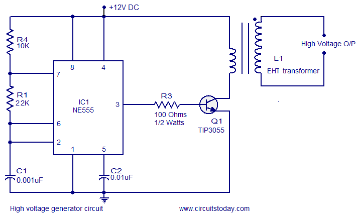
This circuit is highly dangerous due to its output voltage, which is in kilovolts and poses a significant risk of serious injury or death. It should only be attempted by individuals with extensive experience in handling high voltages. No...