
MC81 holiday lights ASIC
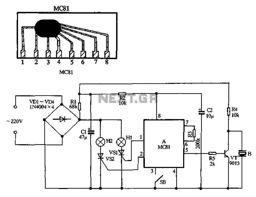
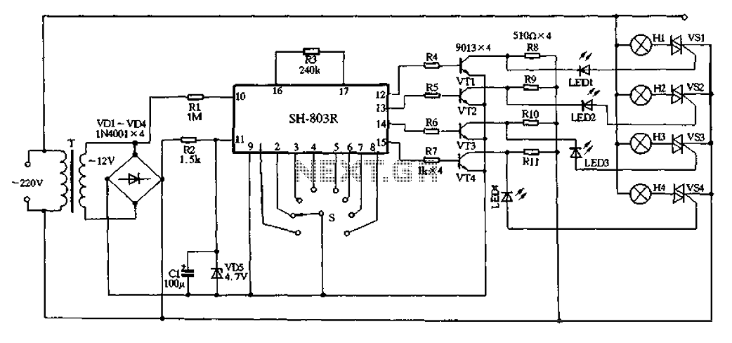
A 220V AC power supply is integrated into the circuit, utilizing a VDI ~ VD4 bridge rectifier to convert the AC voltage into a usable DC format. This rectified voltage powers two indicator lights, Hl and H2, which serve as visual signals within the system. The inclusion of resistors Rl and R2 is critical, as they limit the current flowing to the capacitors C1 and C2. These capacitors function as filters in the power supply, smoothing out voltage fluctuations and ensuring stable operation.
The internal MC81 regulators are a notable feature, as they allow the circuit to function effectively without necessitating an external voltage regulator. However, for optimal performance, it is recommended to include a current-limiting resistor to prevent excessive current from damaging the components.
The circuit design incorporates a manifold that drives SCRs (Silicon Controlled Rectifiers) VSI and VZ, which are responsible for controlling the flashing of the indicator lights. This setup allows for dynamic light patterns that can enhance the visual appeal of the circuit.
For audio output, a 5-pin connection is utilized to amplify the music signal through an external transistor (VT). This transistor drives a piezoelectric ceramic speaker (B), which produces sound. The circuit is configured to enhance the sound volume of the piezoelectric ceramics by utilizing resistor R1 as a voltage supply, ensuring that the sound output meets the desired specifications.
The user interface includes a button switch (SB) that does not lock, allowing users to change the light and music settings with each press. This feature provides flexibility in adjusting the volume levels between large, medium, and small settings, enhancing the user experience by allowing for immediate changes without the need for specific selection mechanisms. Overall, this circuit effectively combines visual and auditory elements, making it suitable for various applications requiring synchronized light and sound output.220V AC by VDI ~ VD4 bridge rectifier, lights the way for Hl, H2 electricity, another pass Rl, R2 two resistors buck, limiting the capacitor CI, C2 filter manifold A power supp ly (due to internal MC81 Regulators have been, so the external circuit without providing the regulator, but the need to add a current limiting resistor buck). Manifold l, 2 feet directly drive SCR VSI, vsz to control lights flashing string Hl and H2. 5-pin output music signal amplification through external transistor VT to drive the piezoelectric ceramic hair B sound.
To increase the sound volume of piezoelectric ceramics, the power transistor using only R1 a resistance voltage supply. SB no lock button switch, each press to change the light-hop music with the size, can sound large, medium and small between no choice.
Related Circuits

Most cars lack delayed interior lights. The presented circuit addresses this issue by gradually switching the interior lights on and off. This feature facilitates activities such as locating the ignition keyhole after the car door has been closed. The...
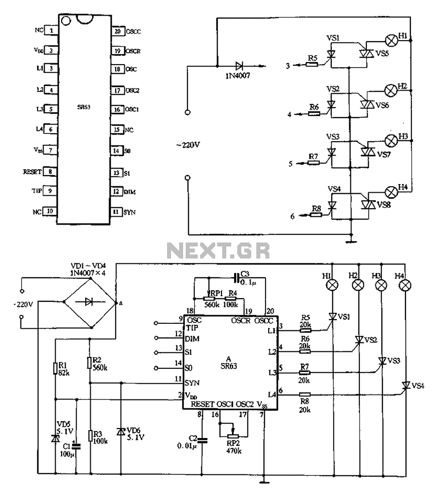
220V AC is converted to DC after passing through a VDI ~ VD4 bridge rectifier. The output from one point supplies power directly to lights H1 through H4. Another route passes through R1, a buck converter, and VD5, which...
This firmware is intended to run on an Atmel ATtiny2313 operating from a 4, 8, 10, 16, or 20 MHz clock or an AT90S2313 operating from a 4 MHz clock. As far as I have been able to determine,...
Here the popular 555 timing IC is wired as a monostable. The timing period is precise and equivalent to: 1.1 x R1 x C1. With component values shown this works out at approximately 1.1 msec. The output duration is...
The silicon controlled rectifier (SCR), commonly referred to as a thyristor, functions similarly to a diode. When the cathode is negative relative to the anode, current can flow. The silicon controlled rectifier (SCR) is a semiconductor device that plays a...
22V AC is supplied through thyristors VSl to VS4 for lighting control. The current is routed through transformer T, followed by rectification using diodes VD1 to VD4, and regulated by VD5 to provide a filtered output of approximately 4.7V...