
mechatronics Design

The control system architecture of the robot integrates multiple components to achieve precise movement and targeting capabilities. The Motorola 68HC11 microcontroller serves as the central processing unit, interfacing with various input and output devices through the MC11 I/O board. The motor control subsystem utilizes the DS3658 stepper controller, SN754410, and LMD18200T h-bridges, which facilitate driving the motors that maneuver the robot and operate the catapult mechanism.
Infrared sensors are strategically positioned to detect beacons, with the three-sensor configuration allowing for directional discrimination. The physical reflectors/blinders enhance the sensors' ability to isolate signals from specific angles, improving the accuracy of the robot's navigation. The integration of ultrasonic rangefinders adds a layer of spatial awareness, enabling the robot to measure distances accurately and adjust its actions based on the calculated distance to the rear wall.
The catapult mechanism is powered by a dedicated 18V supply, ensuring that the high current demands do not interfere with the microcontroller and sensor operations. The output circuitry converts light intensity into a DC voltage, which is further processed to provide a clear indication of light levels through the use of an LED as a rectifier. This design choice allows for immediate visual feedback regarding sensor performance.
The software architecture is modular, with distinct modules handling specific functionalities such as sensor readings, motor control, distance calculations, and shooting operations. The implementation of custom timer modules demonstrates an advanced understanding of timing requirements for the ultrasonic rangefinder, ensuring precise measurements and effective control of the robot's movements.
Overall, the combination of hardware and software components creates a robust system capable of autonomous operation on the court, with the ability to adapt to environmental conditions and execute tasks with precision.The robot was controlled with a Motorola 68HC11 on a special MC11 input/output board furnished by the Stanford Smart Product Design Lab (SPDL). The SPDL also furninshed motor controller boards, each consisting of a DS3658 stepper controller, a SN754410 h-bridge, or an LMD18200T h-bridge, with heat sinks and screw-mounts for wires.
Infrared sensors were used to sense the beacons on the court, thus aiming the robot in the right direction to shoot each time. A set of three sensors with physical reflector/blinders to separate left, right, and narrow-view middle were used to home in on the beacons.
Ultrasonic rangefinders were used to sense the distance from the robot to the rear wall of the court, to calculate how far to launch the balls. This also let the robot know what angle it was shooting at, by finding the position perpendicular to the back wall.
The catapult`s DC motor used its own separate power supply (at 18V), because it pulled too much peak current to run simultaneously with the other electronics. The circuit`s output is a DC analog voltage corresponding to the light intensity; the DC voltage is given by rectifying and low-pass-filtering the signal after amplification.
Note that the rectifying diode is an LED, allowing one to look at the circuit and see the intensity of light being read by the sensor, without the use of measuring instruments. The signal is greatly amplified because it is designed to operate with the sensors eight feet from the beacons.
This amplification of a weak signal was also the reason for the second (. 75V) offset voltage: the weak signal, even at its maximum, was below 2. 5V (the first reference voltage) after the voltage drop from the rectifying diode; in order to get any signal, a lower offset voltage had to be used. We used a Devantech SRF04 rangefinder module. It runs on 5VDC, requires a 10us logic-high pulse (TTL-level) to trigger each sample, and returns a logic-high pulse whose duration is proportional to the distance measured.
Pre-existing modules were provided for pulse-width modulation and period modulation of motors; however, we did write such routines from scratch earlier in the course to understand them. A module was provided to handle multiple independent timers. However, since our ultrasonic rangefinder required shorter time increments, Brian wrote his own timer module with help from the professors.
The main program, Robot_main, called the IR_read module to read the IR sensors and compare to see which was brightest, and output the direction which the robot needed to rotate, if at all; the RotateTurret module rotated the robot and kept track of its angular position; the Ultrasound_Sample module handled the sampling of ultrasonic data, while the whole ultrasonic sweep procedure was a subroutine in Robot_main; the distance to shoot was calculated by CalcShootDistance; the shooting, reloading, and pausing between shots was handled by the Catapult module. (See the full text of the program with all its modules below. ) Authorship note: I wrote IR_read, RotateTurret, and CalcShootDistance, as well as most of Robot_main; Ultrasound_Sample and the parts of Robot_main dealing with ultrasonics were written by Brian; Catapult was written by Jeff.
In addition to hardware control and sensor input, the software calculated how far to shoot based on the position of the robot in the court and the position of the basket it was aimed at. (See diagram below. ) The ultrasonic rangefinder was used to find the minimum position to the rear wall, and record the robot`s angular position when perpendicular to the rear wall.
It did this by sampling distances as the robot rotated, creating an array of angular position vs. running average of the last few distance samples, and noting the angular position at the minimum value of averaged distance. The averaging was done to eliminate possible noise variations. The robot swept out an angle of thirty deg 🔗 External reference
Related Circuits
With the fast-paced nature of modern life, the frequency of traffic accidents is also increasing. To enhance vehicle safety, this text presents a mechanically controlled car anti-collision alarm system designed as a single unit. This device integrates real-time control...
The programmable power supply is a component of an integrated test system for guided missiles, designed to provide and test various required stabilized direct current voltage supplies for guided missiles. It features real-time monitoring, overvoltage protection, and automatic overload...
Writing assembly code for microcontrollers (MCUs) can often be a challenging and time-consuming process. However, software development can be streamlined, allowing more time for electronics hardware design by utilizing TINA's Flowchart editor and debugger. This tool enables the generation...
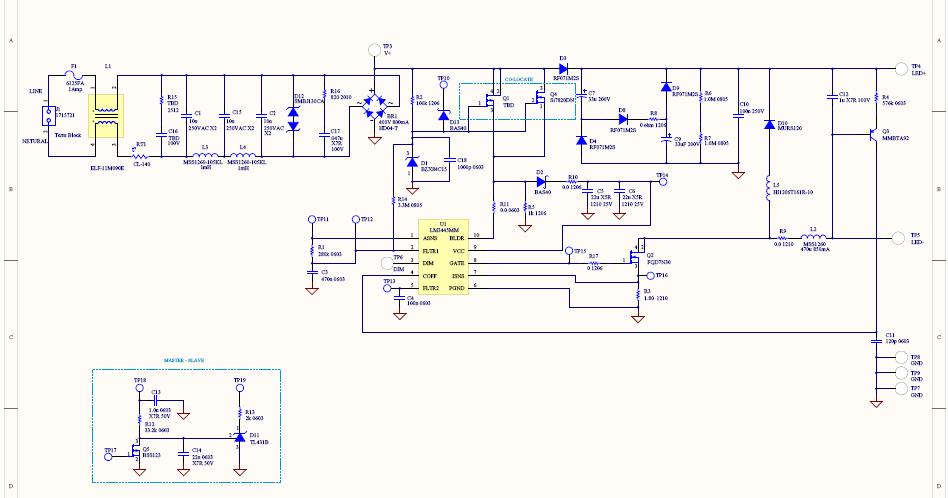
This reference design converts 90V AC to 135V AC input and drives seven or eight series-connected LEDs with an average current ranging from 300 to 600 mA. The LM3445 operates at a nominal switching frequency of 225 kHz. This...
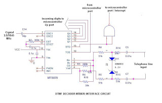
This is a straightforward circuit utilizing the DTMF decoder MT8870 (or CM8870). As illustrated in the circuit, an interrupt will be generated (if the NAND output is connected to the INT of the microcontroller) whenever a call is received...
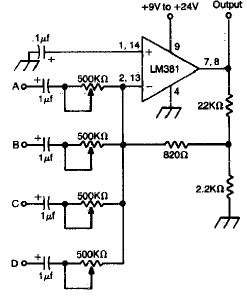
LM381 4-channel audio mixer circuit design project using a few common electronic parts. The LM381 audio mixer circuit is designed to combine audio signals from four separate channels into a single output. This circuit employs the LM381 integrated circuit, which...