
Metal Detectors

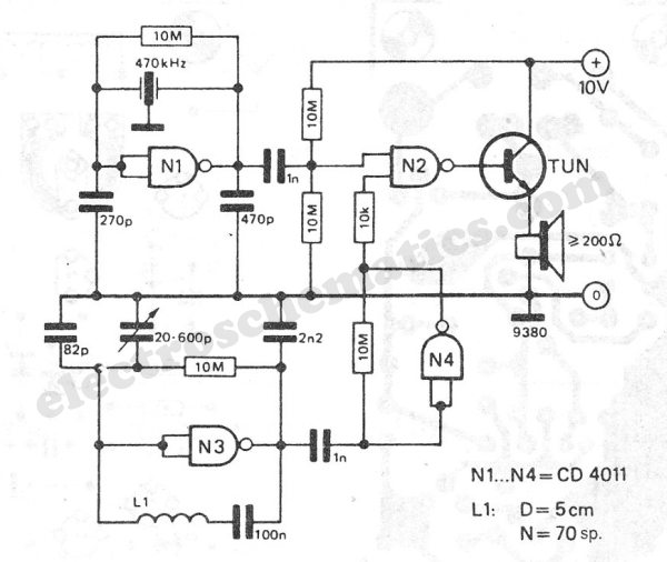
The metal detector circuit is designed to effectively identify metallic objects through its innovative use of superheterodyne technology. The dual RF oscillator setup is essential for generating a stable reference frequency, which is crucial for the detection process. The first oscillator, utilizing a ceramic filter, ensures a clean signal that minimizes interference, while the Colpitts oscillator provides the necessary frequency modulation. The mixer stage, utilizing a transistor, is responsible for combining the two frequencies, producing a beat frequency that is indicative of the presence of metal.
The use of diodes in the detection stage plays a vital role in converting the alternating current (AC) signal from the mixer into a direct current (DC) signal, which can be easily amplified and processed. The low-pass filter further refines the output, eliminating high-frequency noise and ensuring that only the desired signal reaches the audio frequency amplifier. The choice of components, such as the 2822M amplifier, is critical for delivering sufficient power to the speaker, enabling clear audio feedback to the user.
The construction of the inductor L1 is also a key aspect of the circuit, as its inductance directly influences the frequency of the second oscillator. The specified number of turns and wire gauge are optimized to achieve the required inductance for proper operation. The air-core design is advantageous as it reduces losses associated with core materials, enhancing sensitivity and performance in metal detection.
Overall, this metal detector circuit exemplifies a well-engineered approach to detecting metallic objects, combining fundamental electronic principles with practical design considerations to achieve effective performance.The circuit described here is that of a metal detector. The opera- tion of the circuit is based on superheterodyning principle which is commonly used in superhet receivers. The circuit utilises two RF oscillators. The frequencies of both oscillators are fixed at 5. 5 MHz. The first RF oscillator comprises transistor T1 (BF 494) and a 5. 5MHz ceramic filter commonly used in TV sound-IF section. The second oscillator is a Colpitt ’s oscillator realised with the help of transistor T3 (BF494) and inductor L1 (whose construction details follow) shunted by trimmer capacitor VC1. These two oscillators ’ frequencies (say Fx and Fy) are mixed in the mixer transistor T2 (another BF 494) and the difference or the beat frequency (Fx-Fy) output from collector of transistor T2 is connected to detector stage comprising diodes D1 and D2 (both OA 79).
The output is a pulsating DC which is passed through a low-pass filter realised with the help of a 10k resistor R12 and two 15nF capacitors C6 and C10. It is then passed to AF amplifier IC1 (2822M) via volume control VR1 and the output is fed to an 8-ohm/1W speaker.
The inductor L1 can be constructed using 15 turns of 25SWG wire on a 10cm (4-inch) diameter air-core former and then cementing it with insulating varnish. For proper operation of the circuit it is critical that frequencies of both the oscillators are the same so as to obtain zero beat in the absence of any metal in the near vicinity of the circuit.
The alignment of oscillator 2 (to match oscillator 1 frequency) can be done with the help of trimmer capacitor VC1. When the two frequencies are equal, the beat frequency is zero, i. e. beat frquency=Fx-Fy=0, and thus there is no sound from the loudspeaker. When search coil L1 passes over metal, the metal changes its inductance, thereby changing the second oscillator ’s frequency.
So now Fx-Fy is not zero and the loudspeaker sounds. Thus one is able to detect presence of metal. 🔗 External reference
Related Circuits
Most metal detectors operate on the principle that metals within a magnetic field alter the behavior of that field. There are two primary methods for detecting these changes. In one method, an alternating current is supplied to a transmit...
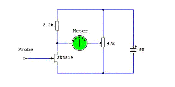
The sensitivity of the gate terminal to voltage changes is significant. In this configuration, the gate terminal is left open circuit and connected only to a probe, which consists of a few inches of bare copper wire. Without a...
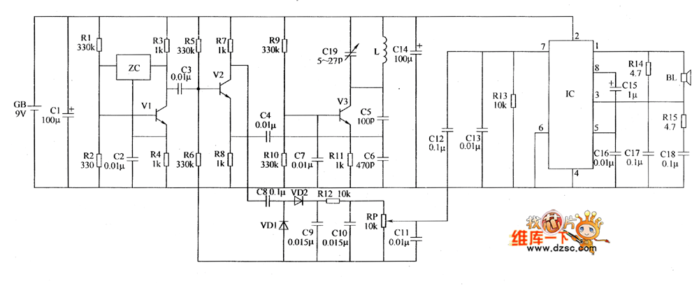
The metal detector circuit includes a fixed frequency oscillator, mixer, detector, detection oscillator, and power amplifier circuit. The fixed frequency oscillator circuit is composed of a ceramic filter (ZC), transistor (V1), resistors (R1 to R4), capacitor (C2), and other...
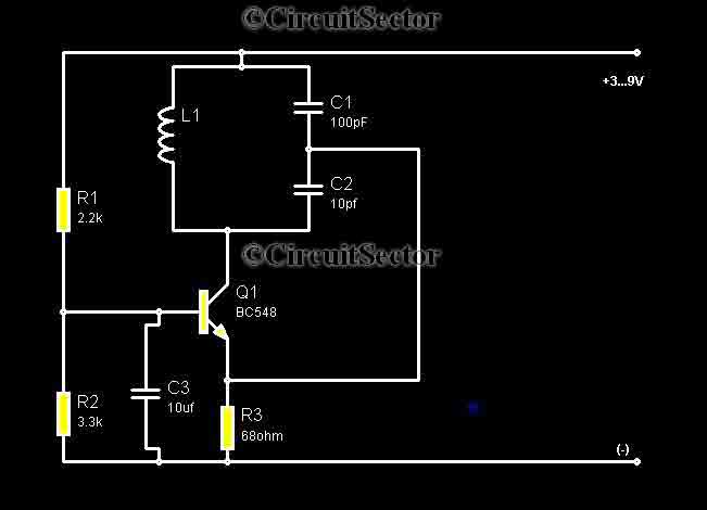
Metal detectors are usually very complicated and it may be consist of very costly components and metal detector DIY circuits are rare. However this metal detector hobby circuit can be constructed by only a few components such as BC548...
The working principle of this inexpensive and simple-to-build metal detector circuit involves mixing two equal frequencies, which results in a low-frequency interference. The metal detector circuit operates on the principle of heterodyning, where two frequencies are combined to produce a...
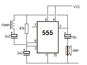
This metal detector electronic project schematic circuit is designed using a simple 555 timer integrated circuit. The schematic circuit requires a few external electronic components. The metal detector circuit utilizes the 555 timer IC in astable mode to generate a...