
pulse induction metal detector with DSP

The pulse induction metal detector circuit comprises several key components. The transmit coil is connected to a power source through a switching mechanism, which allows for the rapid on-off cycling necessary to create the magnetic pulses. The receive coil is connected to an analog front end (AFE) that amplifies the signals induced by eddy currents in nearby metals. The output from the AFE is fed into a digital signal processor (DSP), which performs signal analysis, filtering, and discrimination of the detected signals. The DSP can be programmed to recognize specific patterns indicative of different metal types, enhancing the detector's ability to differentiate between ferrous and non-ferrous materials.
To optimize performance, the design includes a microcontroller that manages the timing of the pulse generation and signal processing, ensuring that the system operates efficiently. The choice of components, such as operational amplifiers for signal amplification and analog-to-digital converters (ADCs) for digitizing the received signals, is critical for achieving high sensitivity and accuracy.
The power supply design is also crucial; using a single battery pack with a DC/DC converter minimizes complexity while ensuring adequate voltage levels for the operation of both the transmit and receive circuitry. Careful consideration of the layout and grounding of the circuit is necessary to minimize noise and interference, particularly in high-frequency applications. Overall, this comprehensive approach to designing a pulse induction metal detector aims to achieve reliable performance across various detection scenarios, with a focus on metal discrimination and depth detection.Most metal detectors work on the fact that metals in a magnetic field change the behaviour of the field. There are two general approaches to detect these changes. In one approach, an alternating current is provided to a transmit coil. A receive coil is used to pick up the magnetic field generated by the transmitter. If a piece of metal comes inside the range of the magnetic field lines, the receive coil can detect a change in both amplitude and phase of the received signal. The amount of amplitude change and phase change is an indication for the size and distance of the metal, and can also be used to discriminate between ferrous and non-ferrous metals.
In the other approach, current pulses are sent to the transmit coil. The magnetic field caused by these pulses start eddy currents in metals close to the coil. If the magnetic field is switched of fast enough, the eddy currents can be detected with the transmit coil, which then acts as a receiver. Pulse induction can often reach deeper targets than frequency based detectors, but discrimination between different types of metals is more difficult.
Because of the specific needs when I started this project, this page describes a pulse induction metal detector with as much as possible discrimination between different metals. To achieve this, the processing of the signals is done entirely digitally with a digital signal processor, DSP.
There are many projects floating around on the internet regarding pulse induction metal detectors. Although they differ in the way the signals are processed, the electronics which generate the magnetic field pulses is almost always identical. The main part to generate magnetic pulses is the coil. The size of the coil is mainly dependent on the required detection depth and the minimum size of objects that still should be detected.
In general you can say that the maximum theoretical detection depth of a coil is five times the diameter and the minimum size of an object detected with a coil is five percent of the diameter. These are maximum values and depend heavily on the situation. It is obvious that with a one meter coil you won`t detect a five centimeter object at five meters deep.
It gives however an idea what type of coil you need for a specific problem. Many people will use metal detectors to search for coins and jewelry. For those situations a 250 or 400 mm coil will do. In my situation I needed to locate iron 100 mm watertubes at a depth of two meters. That`s why I decided to go for a 1 meter coil. Although the physical size and shape of the coil may vary (square or elliptical coils are used in specific situations and work just as well as round ones), the inductance of coils only varies slightly between different physical designs. The commonly accepted optimal inductance for search coils for pulse induction metal detectors is in the range of 300 to 500 µH.
For this project I will assume that the coils used are 400 µH. For smaller coils, this in general means a larger number of turns. The search coil should be operated from commonly available power sources. Because of the analog circuitry to amplify the small eddy current signals picked up after the magnetic pulse has been stopped, a double power supply of ±10Volt or ±12Volt is most practical. The coil will only be charged with one of the two power supply sides, which gives an asymmetrical battery discharge if we use two separate battery packs for the positive and negative side of the power supply.
We therefore will only use one battery pack of 10 or 12Volt and generate the other side of the power with a DC/DC converter. Although this is done in most commercial and homebrewn metal detector circuits, it is less than ideal.
The main problem is that the voltage generated by the DC/DC converter is not ripple free, and especially at the high frequencies we are working with, this may cause some unwanted coupling. We will postpone this problem 🔗 External reference
Related Circuits
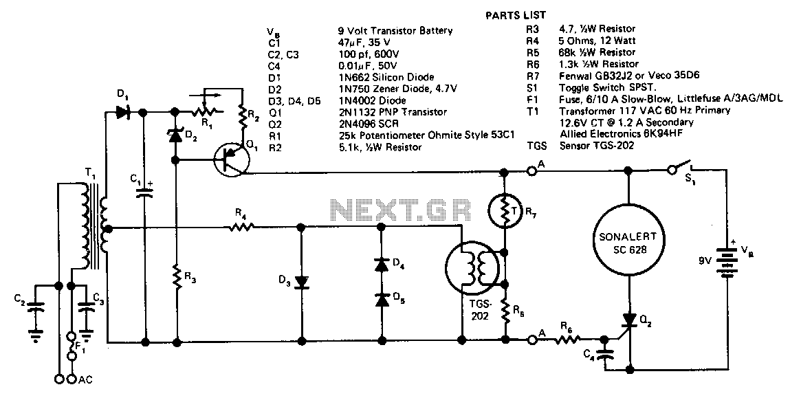
Transformer T1 provides power to the sensor's heater. Due to the sensor's high sensitivity to heater voltage, diodes D1, D4, and D5 regulate this voltage. T1, in conjunction with D1 and C2, forms a DC power supply, with current...
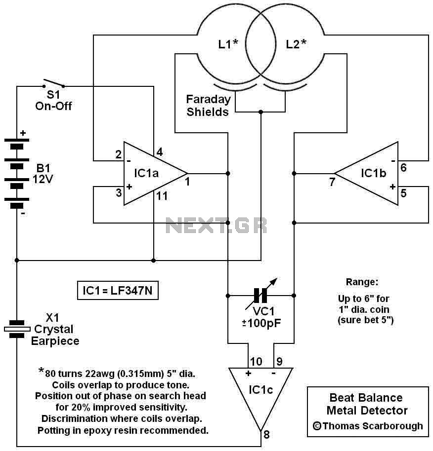
Here's a metal detector circuit that frequencies of the two oscillators are then mixed in similar fashion to BFO, to produce an audible heterodyne. On the surface of it, this design would seem to represent little more than a...
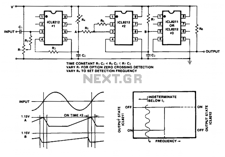
Simple frequency limit detectors providing a GO/NO-GO output for use with varying amplitude input signals may be conveniently implemented with the ICL8211/8212. In the application shown, the first ICL8212 is used as a zero-crossing detector. The output circuit consisting...
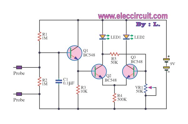
This is a false capture circuit or lie detector circuit. The basic principle is based on the resistance of human skin. While dry skin has a resistance of about 1 Megaohm. The lie detector circuit utilizes the principle of galvanic...
This ion detector circuit is designed to sense static charges and free ions present in the air. It is capable of detecting the presence of free ions, static electricity, or high voltage leakage. The project utilizes a short whip...
This is a straightforward infrared detector circuit designed to detect infrared light. The circuit comprises only three components: an RS-276-145 photo transistor, a 330-ohm resistor, and a general-purpose LED (Light Emitting Diode). When the photo transistor receives infrared light...