
Microprocessor power supply watchdog

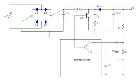
The circuit is designed to ensure reliable operation of the microprocessor by monitoring the regulated 5 V supply. The full-wave bridge rectifier converts AC voltage to DC voltage, which is then smoothed by the resistor-capacitor network formed by Rs and Cj. This network produces a triangular waveform that fluctuates with the supply voltage. The characteristics of this waveform are critical, as the lowest point of the triangular wave is used to determine when the voltage has dropped below an acceptable level.
The LM10C voltage reference provides a stable reference against which the triangular waveform is compared. The feedback network composed of resistors Rn and Rm is configured to establish a threshold voltage of 3.4 volts, which is set to 90% of the minimum voltage of the triangular waveform. This ensures that the reset condition is triggered with a margin, preventing premature resets during normal operation.
When the voltage at the non-inverting input of the comparator dips below this threshold, the comparator output transitions to a low state. This output is connected to the reset pin of the microprocessor, effectively resetting it to prevent erratic behavior caused by inadequate supply voltage.
Capacitor Ch plays a crucial role in the reset timing. It charges slowly through resistor Rk, allowing a delay in the reset signal, which provides time for the supply voltage to stabilize. Once the reset condition is triggered, capacitor Ch discharges quickly through diode De, ensuring a rapid reset of the microprocessor. The inclusion of diode Dg in the circuit prevents unwanted interactions between capacitors Cj and Ck, maintaining the integrity of the voltage monitoring function.
Overall, this circuit is essential for maintaining the stability and reliability of the microprocessor in environments where supply voltage fluctuations may occur. By implementing a well-designed voltage monitoring and reset circuit, the risk of microprocessor failure due to voltage drops is significantly reduced.The circuit monitors the input to the microprocessor 5 V regulated supply for voltage drops and initiates a reset sequence before supply regulation is lost. In operation, the resistor capacitor combination Rs and Cj form a short time constant smoothing network for the output of the fullwave bridge rectifier.
An approximately triangular, voltage waveform appears across C and Rs and it is the minimum excursion of this that initiates the reset. Diode Dg prevents charge sharing between capacitors Cj and Ck. Resistors Rn and Rm form a feedback network around the voltage reference section of the LM10C, setting a threshold voltage of 3.4 volts.
The threshold voltage is set at 90% of the minimum voltage of the triangular waveform. When the triangular wave trough, at the comparator's non-inverting input, dips below the threshold, the comparator output is driven low. This presents a reset to the microprocessor. Capacitor Ch is charged slowly through resistor Rk and discharged rapidly through diode De.
Related Circuits
The design of the AC to DC front stage boost converter in discontinuous mode involved several steps. Initially, the specifications were defined. Subsequently, research was conducted, and the basic power factor correction circuit was analyzed. Finally, the boost converter...
It is important to note that there is limited protection circuitry and fuses in this amplifier. A short turn-on delay for the output power supply is included to minimize thumps, along with a couple of line fuses, but no...
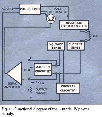
By combining switching and series-pass techniques, the designer of this high-voltage supply achieved 0.01% regulation at power levels up to 100W. The high-voltage power supply employs a hybrid approach that integrates both switching and series-pass regulation methods to achieve exceptional...

A repertory dialer phone contains a library of phone numbers that can be entered and dialed, allowing access to up to fifteen frequently used numbers. It also includes the capability to store the last dialed number or an additional...
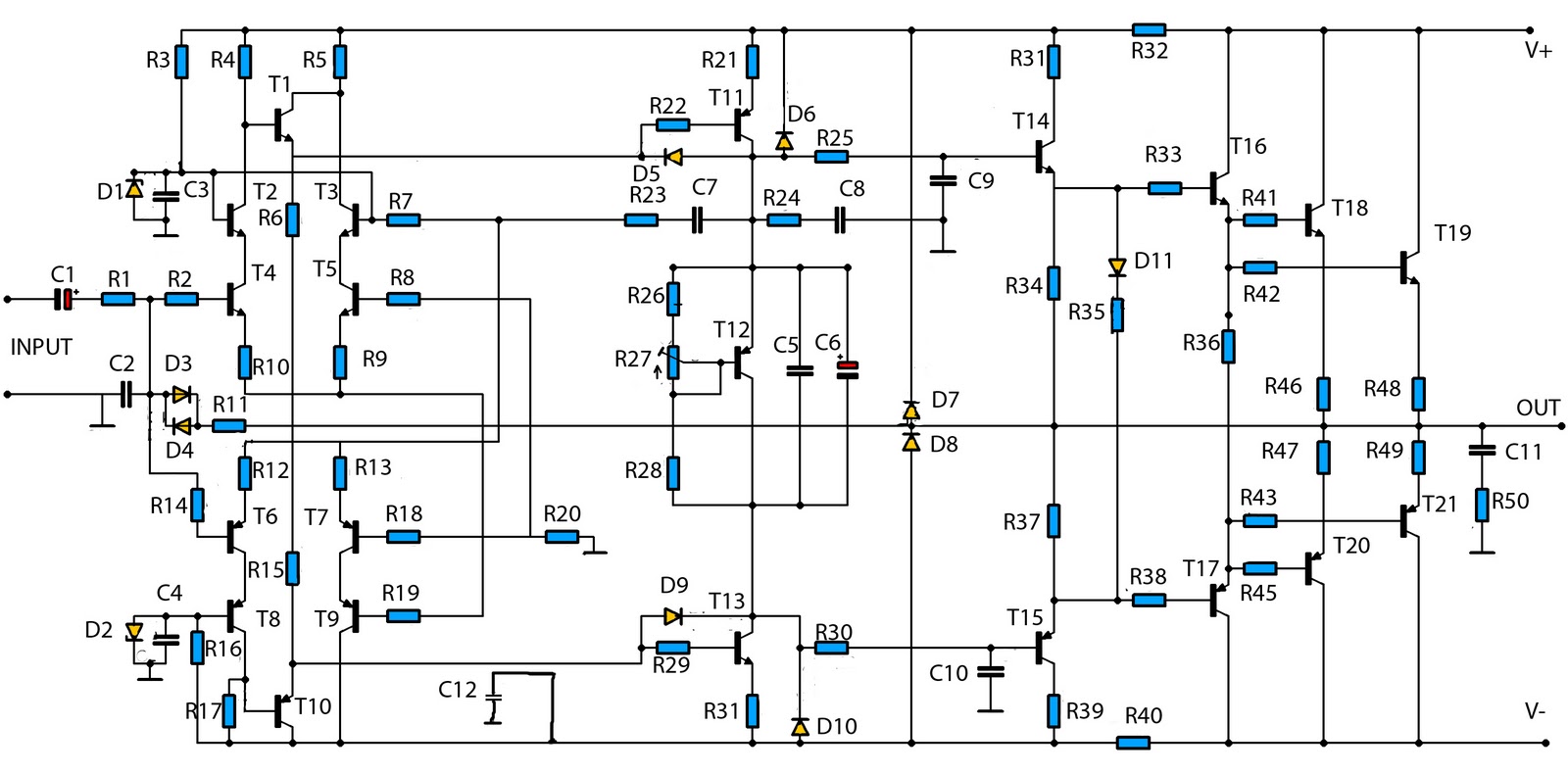
This is a mono amplifier circuit with a high output power of 1400W. It is well-suited for use in large rooms with woofer and full-range speakers, delivering a loud and clear sound with minimal noise. The amplifier utilizes high-quality...
The two circuits below illustrate opening a relay contact a short time after the ignition or light switch is turned off. The capacitor is charged and the relay is closed when the voltage at the diode anode rises to...