
mighty mite
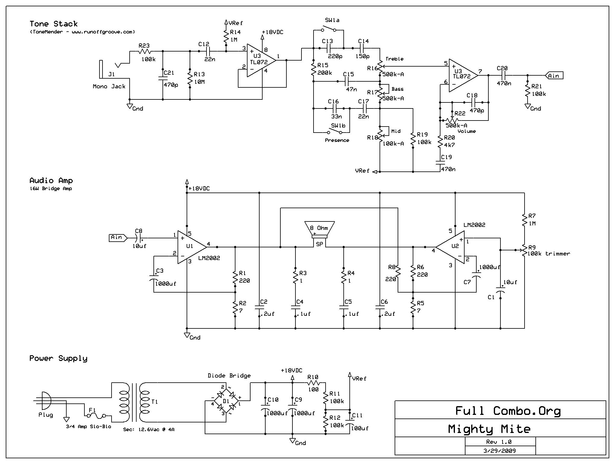
The project involves the culmination of extensive research and development efforts focused on designing a practice guitar amplifier. The amplifier is intended to provide musicians with a portable and user-friendly solution for practicing guitar in various environments.
Key components of the amplifier design include a compact chassis that houses the power supply, preamplifier, tone control circuit, and power amplifier stages. The power supply is designed to accommodate a range of input voltages while ensuring stable output for consistent performance.
The preamplifier stage is critical for amplifying the weak signal from the guitar pickups. It employs high-gain operational amplifiers to ensure clarity and fidelity of the sound. The tone control circuit allows users to adjust bass, midrange, and treble frequencies, providing flexibility in shaping the guitar tone to suit individual preferences.
The power amplifier stage is designed to deliver sufficient output power while maintaining low distortion levels. This stage typically utilizes Class A or Class AB amplification techniques, which are known for their sound quality and efficiency.
The amplifier also includes features such as a headphone output for silent practice, an auxiliary input for connecting external audio sources, and built-in effects like reverb or delay to enhance the overall sound experience.
The completion of this project signifies a significant milestone in the field of guitar amplification, combining decades of advancements in electronic components and circuit design to produce a reliable and high-quality practice amplifier.The completion of a 35 year project to build a practice guitar amp.. 🔗 External reference
Related Circuits
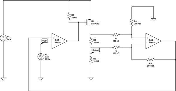
Create a 0-25 mA current limiter using a control voltage input of 0-5 V to regulate the current through a resistive load (R2), which can vary between 0-200 ohms. The O2 operational amplifier (op-amp) functions as a differential amplifier...
To provide rapid motor speed changes and motor direction reversal, four outputs drive a MOSFET H-bridge. N-channel devices serve as the lower rail power MOSFETs, while P-channel devices are utilized as the upper MOSFETs. All MOSFETs are controlled by...
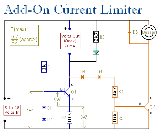
This circuit establishes a maximum limit on the current available from the output terminals by controlling the maximum current that can flow through Q1. The output terminals are in series with Q1, meaning that limiting the current through Q1...
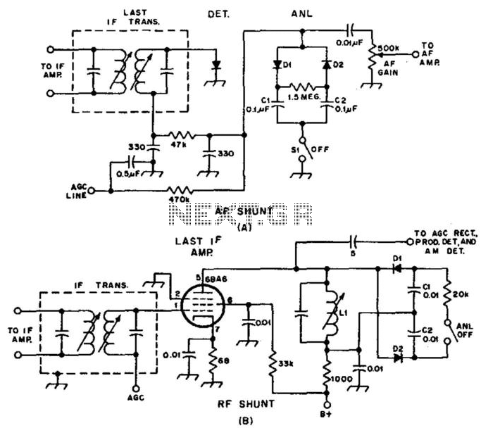
Examples of RF and audio ANL circuits. Positive and negative clipping occurs in both circuits. The circuit is self-adjusting. This noise limiter operates at the IF output. Adequate gain is needed at the IF frequency so that several volts...
This simple circuit and program listing allows the Maximite microcomputer (SILICON CHIP, March-May 2011) to control a stepper motor. It can be expanded to control multiple motors, using four of the Maximite's external I/O pins for each motor with...
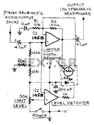
The level at which the limiter activates in audio can be adjusted using the LIMIT LEVEL selector knob. When this threshold is surpassed, the output of the half-limiting detector within the op-amp, functioning as a comparator, triggers the LED,...