
Mini MW Transmitter

The SW transmitter circuit utilizing the IC BEL1895 is designed for operation within the shortwave HF band, specifically between 6 MHz and 15 MHz. This frequency range is optimal for short-range communications, making it suitable for both educational purposes and practical applications. The circuit architecture includes a microphone amplifier that captures audio signals, a variable frequency oscillator that generates the carrier wave, and modulation amplifier stages that modulate the audio signal onto the carrier wave.
Transistor T1 (BF95) plays a crucial role in the amplification process, ensuring that the transmitted signal is strong enough to be received effectively. The simplicity of the circuit is highlighted by its requirement of only two transistors, which significantly reduces complexity and cost. The use of ceramic capacitors, particularly the NP0 1% type, is recommended to maintain stability and performance; however, flexibility is allowed in component selection, provided that electrolytic or tantalum capacitors are avoided.
The mini FM transmitter designed by Tony van Roon exemplifies an accessible project for enthusiasts, enabling transmission that can be received by standard FM radios. Its effective range of approximately 1/4 mile (400 meters) can vary based on environmental factors such as line-of-sight and physical obstructions. Additionally, the circuit operates at a fixed frequency of 12 MHz, eliminating the need for an LC tuned circuit, which simplifies the design further.
The schematic diagram designed by Paul K. Sherby for a 4-transistor FM transmitter includes a detailed components list, which specifies resistor values (e.g., R1, R2, R8 at 1K; R3 at 100K; etc.), diode specifications (D1 = 1N4002), and transistor types (Q1, Q2 = 2N3904; Q3, Q4 = 7001, NTE123AP). This level of detail is essential for builders to accurately replicate the circuit.
The power supply requirements are modest, with an operating voltage range between 1.1 to 3 volts and a low power consumption of 1.8 mA at 1.5 volts. This efficiency allows for a maximum operational range of 30 meters, making it a practical choice for a variety of applications. The inclusion of a PCB layout facilitates the construction process, providing a clear guide for component placement and soldering, ensuring that builders can successfully create this compact and efficient FM transmitter.Here the SW transmitter circuit based on IC BEL1895. This particular transmitter circuit works in shortwave HF band (6 MHz to 15 MHz), and can be applied for shortrange communication and for educational purposes. The circuit is composed of a mic amplifier circuit, a variable frequency oscillator, and modulation amplifier stages.
Transistor T1 (BF1 95) is. Simple and easy build of FM transmitter circuit. The circuit only require 2 transistors. Circuit Notes: Typically the default for the capacitors model is ceramic, preferably the npo 1% type or equivalent. However, generally almost nothing critical right here. Work with any capacitor you`ve laying arround, but DO NOT use any electrolytic or tantalum. This is a mini FM transmitter built and powered using 2 transistors, designed by Tony van Roon. This small transmitter is simple to build and its transmissions could be picked up on any common FM radio.
It possesses a range of approximately 1/4-mile (400 meters) or even more, depending on the line-of-sight, obstructions by big. Here the short wave AM Transmitter circuit design diagram. The circuit is quite simple and easy to build since it applies only a few electronic components. The primary feature of this transmitter is that it really is absolutely free from the LC (inductor, capacitor) tuned circuit and runs using a fixed frequency of 12 MHz.
The following diagram is the schematic diagram of 4 transistors FM transmitter circuit designed by Paul K. Sherby. Components List: R1, R2, R8 = 1K R3 = 100K R4 = 150K R5, R7 = 10K R6 = 220 ohm R9 = 10 ohm P1 = 5K trimpot D1 = 1N4002 Q1, Q2 = 2N3904 Q3, Q4 = 7001, NTE123AP C1.
This is an mini fm transmitter. I think this is the simplest one. Simple, easy and of course. cheap. The supply voltage is between 1. 1 - 3 Volts with power consumption is 1. 8 mA at 1. 5 Volts. This circuit should be able to cover 30 meters of range max. at 1. 5 Volts. Here the PCB Layout:. 🔗 External reference
Related Circuits
This circuit utilizes a 74HC14 hex Schmitt trigger inverter as a square wave oscillator to drive a small signal transistor configured in a class C amplifier setup. The frequency of the oscillator can be either fixed using a crystal...

The most important part of this 88-108 transmitter is the Colpitts oscillator. Capacitors C3, C4, C5, C6, and diodes CD1 and CD2, along with inductor L1, determine the transmission frequency. The RF oscillator. The Colpitts oscillator is a type of...

The circuit consists of a language and sound FM transmitter. It is mounted on a 25mm x 35mm PCB, designed to be placed on a table. When activated by pressing the micro switch SA, the circuit transmits an FM...

Using an NTE288 (or ECG288, GE223, or SK3434), this circuit can key a negative line up to -300 V maximum. Do not use this circuit to key a vacuum-tube amplifier that draws grid current because the keying transistor might...
The RF oscillator employs inverter N2 and a 10.7 MHz ceramic filter to drive the parallel configuration of inverters N4 to N6 via N3. Due to the parallel arrangement of these inverters, the output impedance is low, allowing for...
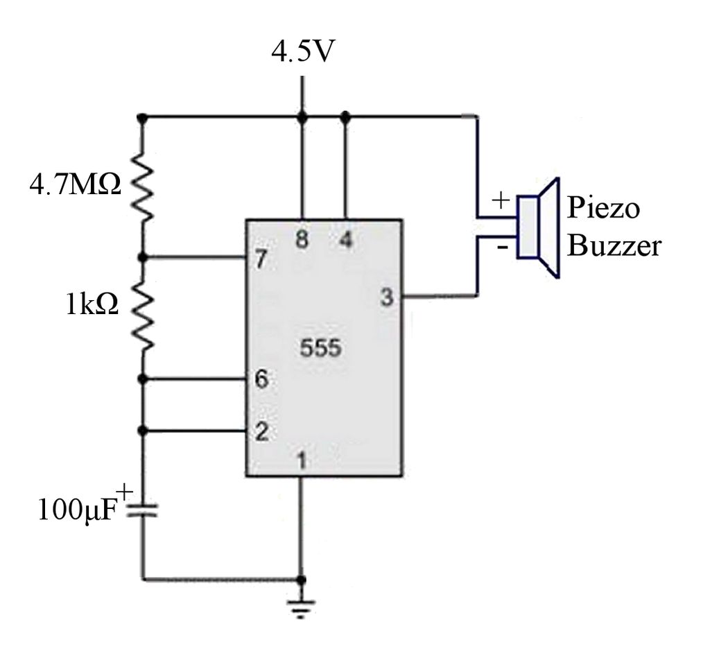
The circuit is a basic 555 timer circuit in astable mode. In this configuration, the integrated circuit (IC) generates a brief pulse to the buzzer at regular intervals. The 555 timer in astable mode operates as an oscillator, producing a...