
Mini USB-DMX interface

The DMX interface circuit is designed to facilitate communication between a DMX controller and various lighting fixtures or dimmers. The choice of an XLR connector is standard in professional lighting applications, ensuring compatibility with existing DMX equipment. The 5-pin XLR connector, while primarily utilizing only three pins for DMX data transmission, provides a robust and reliable connection.
The circuit operates by using the FT232RL chip, a USB to serial converter, which is configured to transmit DMX data frames. The code included in the project file dmx_tx_test.zip establishes the necessary communication protocol, allowing the device to send DMX frames continuously. This is particularly useful for testing and verifying the functionality of DMX fixtures. The ability to set channel values to extremes (0 or 255) simplifies the verification process, as it provides clear voltage levels that can be easily measured with a voltmeter.
The design considerations regarding USB compliance are important, especially in environments where multiple devices may be connected. The FT232RL's capability to enter low power mode is a beneficial feature, yet the MAX481's failure to do so poses a challenge that may require additional circuitry to manage power consumption effectively. The inclusion of logic gates to control the PWREN and SLEEP signals can enhance power management, ensuring that the device adheres to USB specifications.
The potential risks associated with connecting high-power equipment to a PC through a USB interface cannot be overstated. The lack of isolation between the USB port and the DMX line means that any fault in the DMX equipment could lead to damaging the computer's USB port or the entire system. Therefore, proper precautions and understanding of the equipment being used are essential.
The use of surface mount technology in the construction of the circuit demonstrates a modern approach to electronics design, allowing for compact layouts and efficient use of space. The FT232RL chip, being a small SSOP package, requires precision soldering techniques, which can be facilitated by using a microscope. This level of detail in the assembly process is critical for ensuring reliable operation of the circuit.
Overall, this DMX interface circuit represents a practical solution for integrating DMX control into a variety of lighting applications, while also highlighting the importance of careful design and testing in electronic circuit development.On the DMX line side a XLR connector should be used. Either a 5 or 3 pin connector. The pins/holes in a XLR connector are usually numbered so no need for a picture. For the 5 pin connector, only pins 1-3 are used. I used the following code to do some initial tests on the cirquit: dmx_tx_test. zip (Microsoft VC7 project). The code configures the device as a DMX transmitter and repetedly sends out DMX frames until a key is pressed. By setting all channels to either 0 or 255 it was easy to verify that the cirquit was transmitting DMX data using an ordinary voltmeter. The cirquit is not fully USB compliant. The USB spec says that a USB bus powered device must not draw more than 500 uA in USB Suspend mode. FT232RL (IC2) will correctly go into low power mode but MAX481 (IC1) will not. To set MAX481 in low power mode, pins RE and DE on MAX481 must be set to RE="1", DE="0". FT232RL provides both PWREN and SLEEP signals so USB Suspend mode could be handled with some additional gates.
However, all sorts of crazy equipment (which definitely don`t comply with the USB spec) these days use the USB port as power source, so I don`t consider the USB Suspend mode violation too serious. But, here is room for improvements. There are some ready made (commercial) USB-DMX interfaces also using FTDI chips. While designing the cirquit I tried to make it comaptible with the Enttec Open DMX USB, which uses the older FTDI chip FT232BM.
Practical tests shows that my cirquit is compatible with software supporting Enttec Open DMX USB, for example FreeStyler. When working with high power equipment like dimmers, be sure you know what you are doing! You are connecting your PC through the USB port to eqipment that switches kilowatts of power at several hundred volts.
The above cirquit does not isolate the USB port from the DMX line. If everything works correctly and you don`t make any mistakes there is nothing to worry about, but if the DMX port on your dimmer is somehow damaged, or you make a serious mistake somewhere, you might destroy the USB port or in worst case the whole PC. I have a part-time job at the vocational school Yrkesskolan Optima where I have access to surface mounting equipment.
Here are some pictures from the development process. Working (applying solder paste) under microscope is a must, at least with my eyes, when dealing with the FT232RL chip. The 28-pin SSOP chip is so small it fits well on my thumb nail. The reflow oven is, well, small, but it does the job. Surface mounting is a lot of craftsmanship, maybe even more than normal soldering. I find it facinating working under microscope. Below is a picture of the first test with some actual DMX hardware, a 6 channel dimmer. Using my laptop and FreeStyler version 2. 87c configured for the "Enttec open DMX" controller. It works! 🔗 External reference
Related Circuits
One of the more challenging aspects of creating a control or security system that utilizes a PC, such as a burglar alarm, is connecting the sensors to the computer. This typically requires specialized interface expansion boards, and programming that...
Mark the entire scale with the standard metronome steps as follows: 40, 42, 44, 46, 48, 50, 52, 54, 58, 60, 63, 66, 69, 72, 76, 80, 84, 88, 92, 96, 100, 104, 108, 112, 116, 120, 126, 132,...

This page describes a cheap and simple yet flexible HDMI to parallel 3.3V interface. This allows connecting most LCD frames to the BeagleBoard without any further interface required. It is used with some 7-inch 800x480 displays running Angstrom Linux...
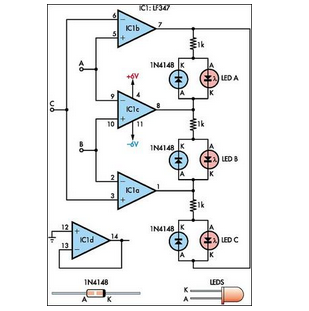
This circuit indicates which of three voltages in the range from approximately -4V to +4V at points A, B, and C is the highest by illuminating one of three indicators. The circuit is designed to compare three input voltages, labeled...
This is my long history the device that controls my home's night light, air-conditioner, etc. The device is a Miniature Real-time Controller. The circuit uses only three chips, a 89C2051, DS275 (or MAX232), and 74LS07 open collector driver. The...
The philosophy behind this minimalist design has been explained by Flavio Dellepiane on his highly interesting site. I have myself written an article about this fleapower amp from Italy in the American magazine AudioXpress. All relevant details are published...