
mixer and vu meter

The circuit design incorporates four 10k resistors (R15, R17, R18, and R19) strategically placed to isolate input channels in an audio mixing application. This isolation prevents the unintended grounding of output signals when one channel's volume is reduced to zero, thus ensuring that both channels remain operational. The resistors are critical in maintaining the integrity of the audio signal, particularly when interfacing with devices that require higher current, such as non-amplified headphones.
The circuit's behavior is governed by Ohm's Law, which explains that increased current draw across these resistors results in a significant voltage drop, leading to diminished audio output and reduced sensitivity on the VU meter. The design has been tested in both breadboard and assembled configurations, revealing the importance of understanding how different output configurations affect signal integrity.
To address the identified issues, potential solutions include experimenting with different resistor values to find an optimal balance that minimizes voltage drop while maintaining the desired audio performance. The exploration of alternative designs that suggest higher potentiometer values as a remedy for attenuation is also underway.
The integration of an LM833 dual op-amp buffer has been implemented to resolve impedance mismatches, although it introduced noise at elevated audio levels. This noise issue may necessitate further refinement of the circuit, including the evaluation of capacitor placements and the power supply configuration.
In summary, the circuit design is a complex interplay of resistive elements and amplification strategies aimed at achieving a robust audio mixing solution. Continued experimentation and research will be essential in optimizing performance and addressing the challenges encountered during development.The 10k resistors in question are R15, 17, 18, and 19 (R16 is somewhere else). Their purpose is to separate the input channels, because otherwise turning the volume control for one channel down to zero would also connect the output signal to ground, cutting out both channels as I discovered when I excluded them which breadboard testing). The origi nal plans called for a 10k resistor on each channel, so I included one. The catch (as I figured out this morning) is that if a significant current is required (such as that needed to power non-amplified headphones), the voltage drop across these resistors increases in accordance with Ohms law. This causes a large drop in the output voltage, which is the reason for both the weak signal output AND the apparent decrease in VU sensitivity.
With no output, or when connected to an amplified output such as a stereo, the current draw is significantly lower, and the VU meter functions normally. With no way to compare the signals between an amplified and non-amplified output, this took a while to click.
Additionally, because I tested the VU meter and the mixer circuit separately on the assumption that one would not impact the other, I didn`t see this effect until I assembled the full board. I`ll do a bit of research, see if I can find a simple solution. Can`t use diodes, because it`s an AC signal (also tested during breadboard prototyping). Probably just use a lower value resistor in the end. As an aside, I really don`t care if people copy anything from this, so I`ll post videos, schematics, anything.
If someone wants to rip off the entire project though, send me a message, I`ve got a spare PCB. This was linked to from some other guys site, who was building his own mixer. As such he excluded the footnote that it was not intended for use with phono level signals, due to the attenuation problems mentioned above, and was only suitable for line level signals (note to self; in future, do some proper research before using someone else`s design). As far as I can tell, I have a few options: Design a second mixer, remove the existing parts and connect the new mixer via wires (or design the PCB for the new mixer to plug into the current pcb header positions) More googling, this time I was searching for an alternative design for the mixer.
During which, I came across this. The operation of the circuit is identical to what I have currently, but more importantly, the author included a footnote that attenuation problems could be lessened by increasing the potentiometer values. I`m not sure if that would actually work, but I`m keen to give it a try. Miniature pots are $8. 50 each at Jaycar cheaper at Element14, but then you have to wait. ) which pales compared to manufacturing a whole new board. I bought a cheapish) 24mm 100K © pot and tried it today; no improvement. So it looks like the amplifier is the way to go. Am I correct in assuming that the amplifier will essentially separate the VU from the output, and so the VU input does not need to be connected to the amplifier output as well In other news, I`m a fair way through mounting everything I have in the case; got the LED`s all lined up, the PCB fixed, and the charging board mounted.
Pot`s are next. Will post photos eventually. Ok, been a while since I`ve made any progress on this but hey, that`s what Uni does. However, seeing as I finally got my hands on the headset I wanted this weekend, and having some time to spare courtesy of the snow, I threw together a buffer from a LM833 dual op amp I found in my IC draw, using this circuit: The good news is that this fixed the impedance problem, as it was designed to do. However it introduces a few lesser problems. When I tried it I noticed a bit of noise at high audio levels. I tried swapping a few capacitors zround, but didn`t hear any change. So acting on a hunch (in absence of an oscilloscope), I plugged a 9V battery in instead of a 4. 5 to see i 🔗 External reference
Related Circuits
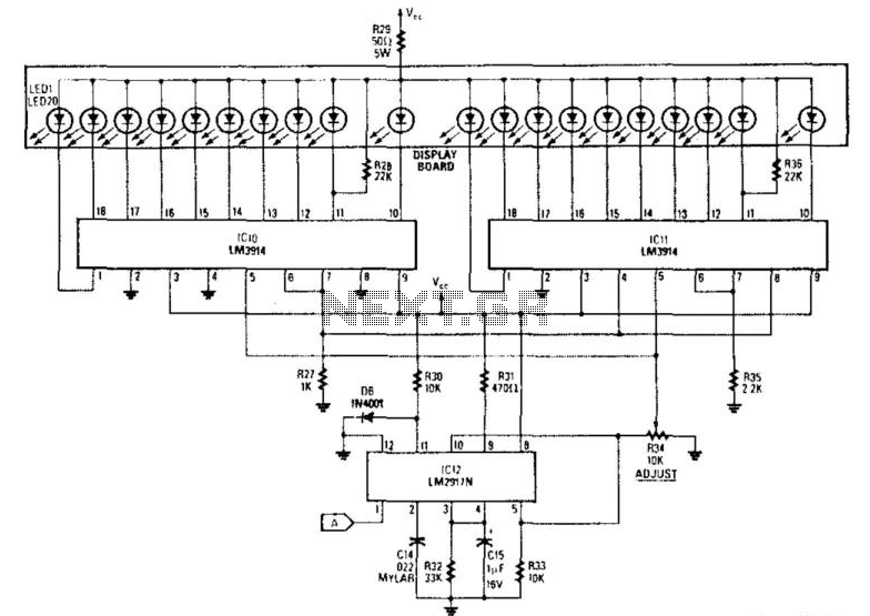
The analog display consists of a frequency/voltage converter (IC12) and bar-graph segment drivers IC10 and IC11. More: R34 is the calibration adjustment and is set so that an engine rpm of 5 000 to 7000 rpm lights the first...
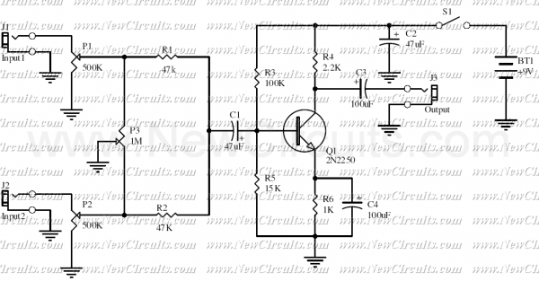
This is a classic signal mixer that is used for audio purpose. VR1 & VR2 are inputs audio volume controllers and VR3 is used to control the balance between Input1 and Input2. Connect a dynamic microphone to Input1 and...
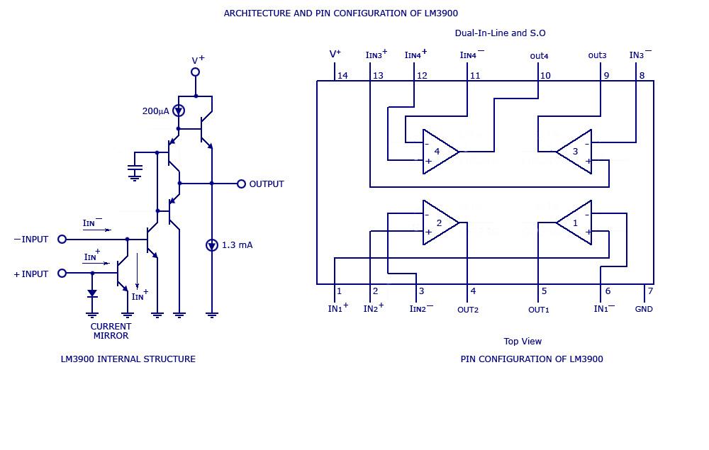
By adding the same circuit in parallel, the number of inputs can be increased according to the applications. Each input is connected to the inverting terminal of the LM3900. The built-in amplifier of each section amplifies every audio input...

The frequency pulses originating from the mains supply are safely insulated by capacitors C1 and C2, along with inductor L1. These pulses are amplified by transistor Q1, while diodes D1 and D2 limit any peak voltages at the input....
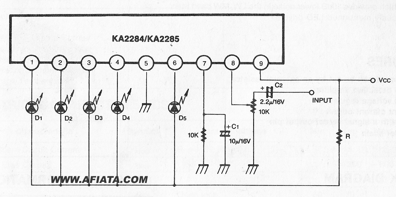
The KA2284 is a monolithic integrated circuit designed for 5-dot LED level meter drives with a built-in rectifying amplifier. It is suitable for both AC and DC level meters, such as VU meters or signal meters. The KA2284 integrated circuit...
This is a straightforward circuit. The first stage functions as a crystal receiver, utilizing a germanium detector diode (such as 1N34, although AA119 is more commonly found in Europe); a silicon diode is not suitable. The operating frequency is...