
VFO/BUFFER circuit
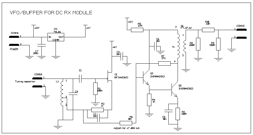
The Hartley oscillator is a type of LC oscillator that utilizes an inductor-capacitor (LC) network to generate oscillations. The circuit typically consists of two inductors and a capacitor, forming a feedback loop that sustains the oscillation. In this configuration, the output power of +7 dBm indicates a strong signal suitable for driving a 50 Ohm load, which is standard for RF applications.
The recommendation against using a gate diode is significant, as the inclusion of such a component can introduce additional non-linearities and noise into the circuit. Phase noise is a critical parameter in oscillator design, particularly in communication systems, where signal clarity and stability are paramount. Ulrich Rohde's insights emphasize the importance of maintaining the oscillator's original design integrity to achieve optimal performance.
The frequency range of up to 10 MHz is typical for Hartley oscillators, but achieving higher frequencies may require careful component selection and layout techniques to minimize drift. The tuning capability through a capacitor or varicap tuning diode allows for fine adjustments to the output frequency, making this circuit versatile for various applications.
When integrating this oscillator with a DC receiver, it is essential to use a screened enclosure to prevent electromagnetic interference (EMI) from affecting the receiver's performance. The enclosure acts as a Faraday cage, shielding the sensitive receiver components from extraneous signals that could introduce hum or microphonics. Additionally, careful routing of signals and the use of twisted pair wiring can further mitigate unwanted coupling.
If the oscillator is designed to operate at half the input frequency and is subsequently passed through a balanced doubler, as seen in the Kanga US version of Campbell's binaural receiver, the need for extensive shielding may be reduced. This approach leverages the harmonic generation capabilities of the circuit, allowing for effective signal processing while minimizing the risk of interference with the receiver's operation.
Overall, the Hartley oscillator presents a robust solution for generating stable RF signals, provided that careful attention is paid to component selection, circuit layout, and enclosure design to optimize performance and minimize noise.It`s basically a standard Hartley oscillator, output is +7 dBm into 50 Ohms. Don`t be tempted to add a gate diode, this circuit doesn`t need it, and it will degrade the phase noise performance, according to Ulrich Rohde. It should be suitable for any frequency up to 10 MHz or more (depending on how good you are at making drift-free oscillators) and may be tuned with a suitable capacitor or varicap tuning diode.
It`s essential that this circuit be built into a suitable screened enclosure if using it with a DC receiver, and steps be taken to ensure that as little as possible of the oscillator signal can get into the receiver input, to minimise hum and microphonics. This won`t be required if the oscillator is run at half the input frequency, and put through a balanced doubler, as is done with the Kanga US version of Campbell`s binaural receiver.
🔗 External reference
Related Circuits
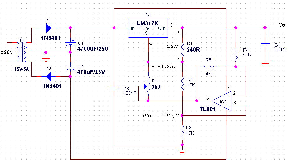
The LM317 is an adjustable, positive 3-terminal voltage regulator capable of supplying 100 mA (for RA87U control) or 1.5 A (for Order Code UF27E and N61CA) across an output voltage range of 1.2 V to 37 V. These voltage...
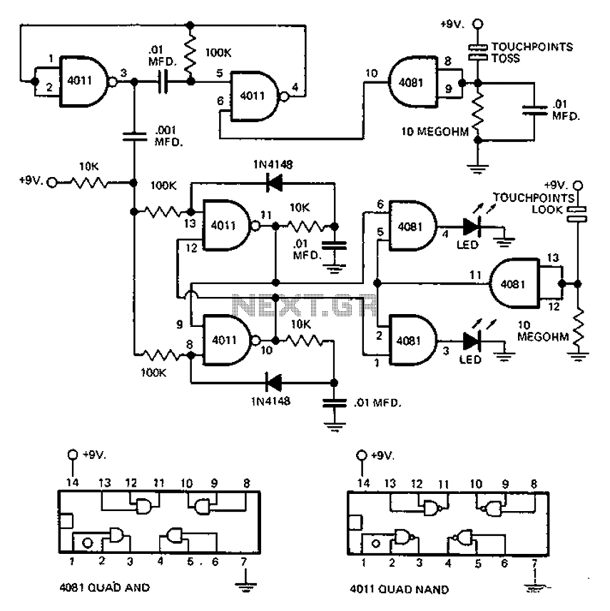
This circuit employs an astable multivibrator to alter the state of a signal based on specific conditions. It also incorporates a flip-flop, which retains the state of the output once a change is detected, completing a cycle of the...
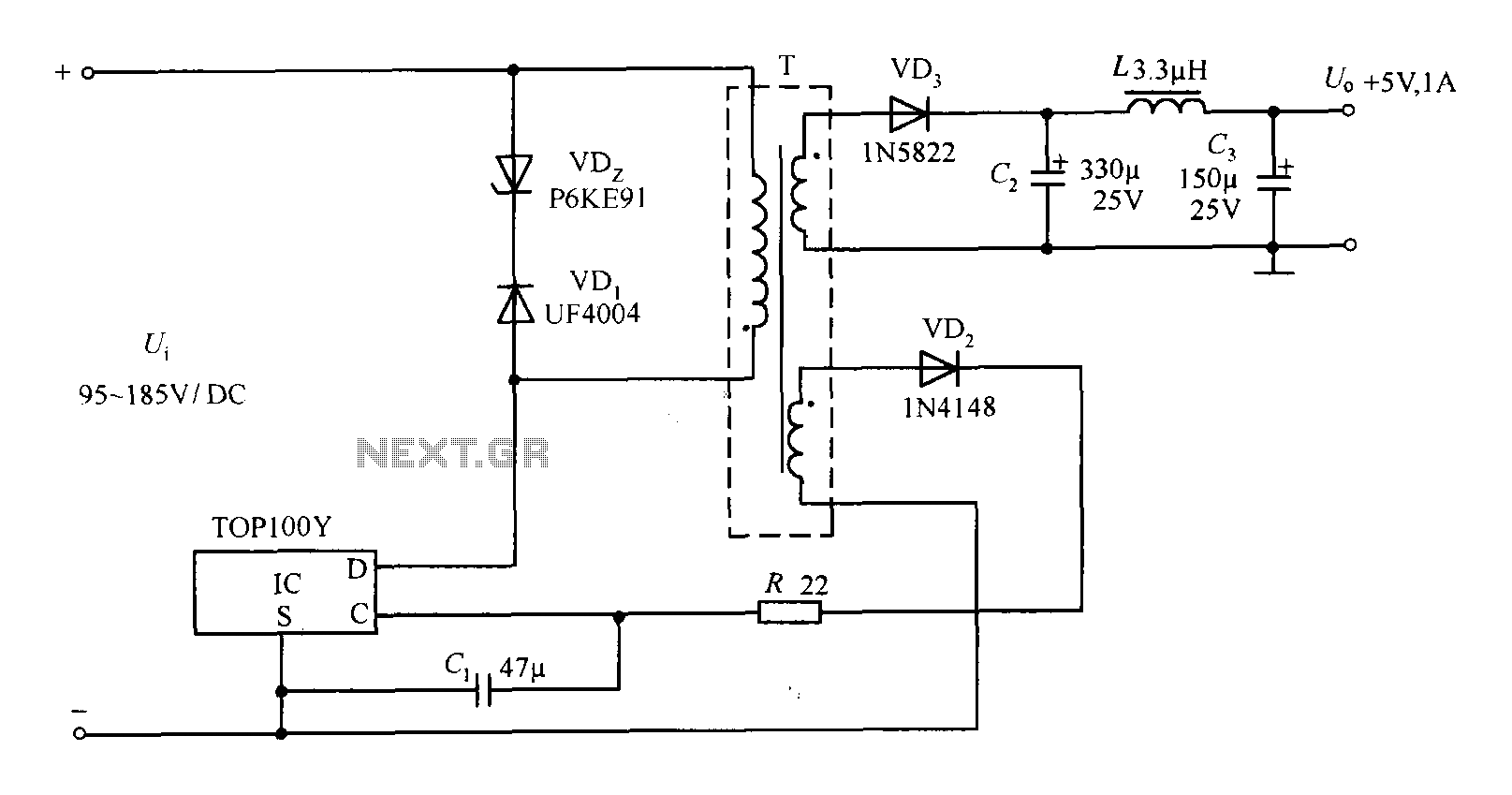
The TOP100Y is a flyback DC switching power supply circuit with a +5V, 1A output. This power supply features a feedback circuit that directly regulates the output voltage, making it suitable for applications that require electrical isolation and minimal...
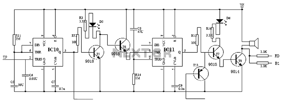
Child lock voltage comparator 555 monostable circuit, a counter, JK flip-flop, UPS power supply design digital logic circuit, electronic door control, and various additional circuitry to ensure the safety circuit can operate with a high safety factor. The circuit...
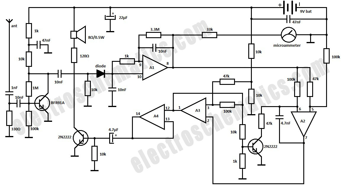
This is a simple RF bug detector designed to identify spy bugs, capable of operating up to 2 GHz. Below are some essential components required for this circuit. The RF bug detector circuit functions by utilizing radio frequency signals...
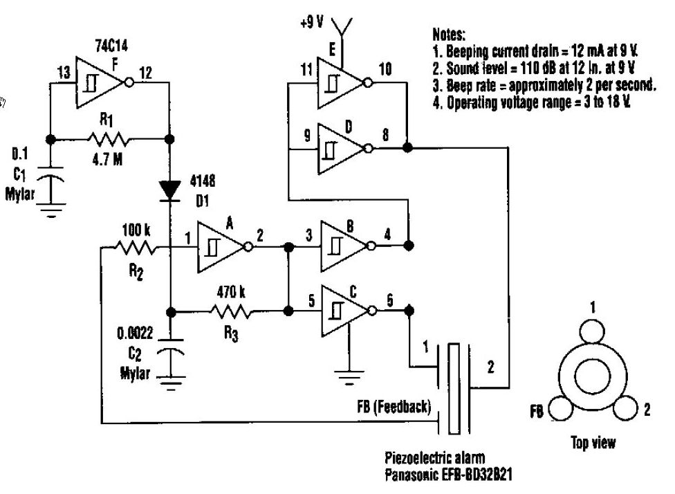
This beeper circuit generates an impressive 110dB sound level from a 9V supply. The design employs a single 74C14 (CD40106B) CMOS hex inverting Schmitt-trigger integrated circuit (IC), which must be paired with a piezoelectric device featuring a feedback terminal....