
Motorcycle Alarm PCB
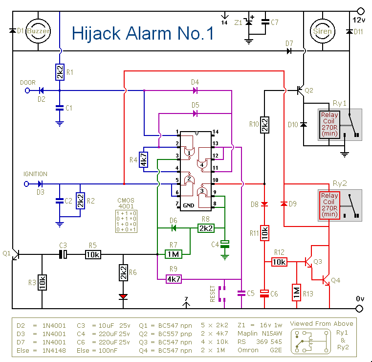
While at least one switch remains closed the siren will sound. About thirty seconds after all of the switches have been opened, the alarm will reset. How long it takes to switch off depends on the characteristics of the actual components used. You can adjust the time to suit your requirements by changing the value of R6 and/or C4. The circuit is designed to use an electronic Siren drawing 300 to 400mA. It`s not usually a good idea to use the bike`s own Horn because it can be easily located and disconnected. However, if you choose to use the Horn, remember that the alarm relay is too small to carry the necessary current.
Connect the coil of a suitably rated relay to the "Siren" output. This can then be used to sound the Horn, flash the lights etc. The circuit board and switches must be protected from the elements. Dampness or condensation will cause malfunction. The components are all drawn lying flat on the board - but those connected between close or adjacent tracks are mounted standing upright. The links are bare copper wire on the component side. The Support Material for this alarm includes a detailed guide to the construction of the circuit-board, a parts list, a complete circuit description and more.
Connect a 1-amp in-line fuse AS CLOSE AS POSSIBLE to your power source. This is VERY IMPORTANT. The fuse is there to protect the wiring - not the alarm. Exactly how the system is fitted will depend on the make of your particular machine - so I`m unable to provide any further help or advice in this regard. The quiescent (standby) current of the circuit is virtually zero - so there is no drain on the battery.
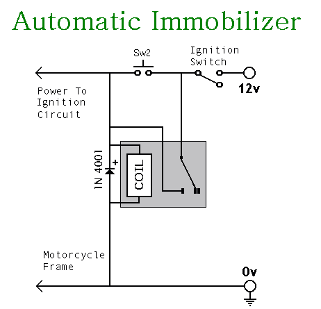
If you want to operate the alarm manually use a key-switch or a hidden switch connected to the "off/set" terminals. For automatic operation connect a wire from the ignition circuit to the "ignit" terminal. Then every time you turn-off the ignition - the alarm will set itself. Remember that this wire from the ignition switch is not protected by your 1-amp inline fuse. So unless its run is very short - fit the wire with its own 1-amp fuse as close as possible to its source.
Before fitting this or any other immobilizer to your bike, carefully consider both the safety implications of its possible failure - and the legal consequences of installing a device that could cause an accident. If you decide to proceed, you will need to use the highest standard of materials and workmanship. Remember that the relay MUST be large enough to handle the current required by your ignition system. Choose one specifically designed for automobiles - it will be protected against the elements and will give the best long-term reliability.
You don`t want it to let you down on a cold wet night - or worse still - in fast moving traffic! Please note that I am UNABLE to help any further with either the choice of a suitable relay - or with advice on its installation. When the ignition is switched on again the relay will not energize. The bike`s ignition circuit will remain broken until you press Sw2. The relay then uses its own contacts to latch itself on. The same contacts complete the connection to the ignition circuit. The design has a number of advantages. It operates automatically when you turn-off the ignition - so there`s no need to remember to activate it.
The relay uses no current while the ignition is off - so there`s no drain on the battery. To de-activate it you`ll need to have the ignition key and you`ll need to know the whereabouts of the push-switch. For extra security Sw2 could be key-operated. 🔗 External reference
Related Circuits
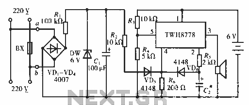
The circuit functions as an AC blown fuse alarm. When the fuse (BX) is intact, 220 V AC voltage passes through a bridge rectifier composed of diodes VD1 to VD4. Resistor R1 limits the current, and the output is...
When the switch is pressed, capacitor C3 charges through resistor R4 with a time constant of 0.47 seconds. Upon releasing the switch, C3 discharges more slowly through resistors R7 and R3, with a time constant of approximately 5 seconds....

This circuit serves as an over-temperature alarm and cooling system utilizing CD4011 four NAND gate integrated circuits to monitor the oven's temperature. In the event of a thermostat circuit failure or power outage, if the internal temperature exceeds or...
Computers often experience overheating due to prolonged use or high ambient temperatures, making temperature controllers essential. Accurate temperature measurement is necessary to ensure that the computer operates within a safe temperature range. A circuit diagram for a simple temperature...
Before installing this or any other engine cut-off device in a vehicle, it is essential to carefully evaluate the safety implications of potential failures and the legal ramifications of implementing a device that could result in an accident. If...

The transistor Q1 remains off until the magnetic switch connected to J1 closes. When this occurs, 9V is supplied through R1 to the base of Q1. As a result, Q1 turns on, which charges capacitor C2 through relay K1,...