
Multi-Tester Logic Probe Signal Tracer And Injector
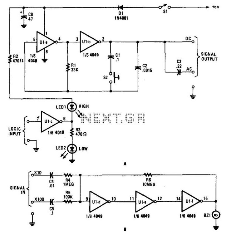
The described circuit serves as a versatile test set designed for signal generation and audio output. The signal injector, represented by operational amplifiers U1A and U1B, is capable of producing two selectable frequencies: 10 kHz and 100 Hz. This selection is facilitated by switch SI, enabling the user to adapt the output frequency based on the testing requirements.
The logic probe, designated as U1C, is integrated into the circuit to provide visual feedback on the logic state of the signals being tested. This component is essential for diagnosing digital circuits, as it indicates high or low logic levels, thus assisting in troubleshooting.
The audio amplifier section includes operational amplifiers U1D, U1E, and U1F. This configuration is specifically designed to drive a piezo sounder element, which operates without an internal driver. By utilizing the piezoelectric effect, the sounder converts electrical signals into audible sound, functioning effectively as a piezoelectric speaker. The absence of an internal driver allows for greater flexibility in the circuit design, as it can be powered directly by the audio amplifier output, ensuring efficient sound production.
Overall, this circuit combines signal generation, logic testing, and audio output capabilities, making it a valuable tool in electronic diagnostics and testing applications. This circuit for a test set contains a signal injector (U1A/U1B) and associated com ponents, a logic probe (U1C) and an audio amplifier. SI selects either 10-kHz or 100-Hz output. U1D, U1E, and U1F form an audio amplifier that drives a piezo sounder element without an internal driver so that it functions as a piezoelectric speaker. 🔗 External reference
Related Circuits
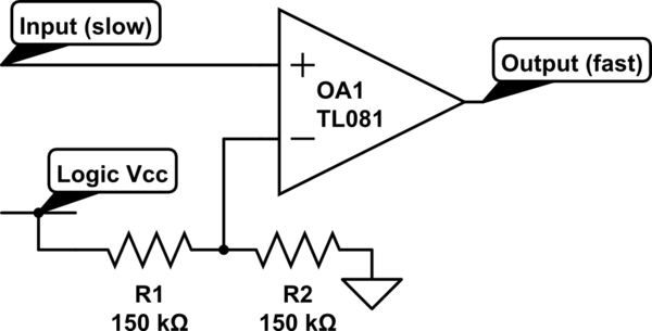
Invert a signal to drive FETs with rapid rise and fall times. It was suggested to use an inverter (not a chip) instead of logic chips, which are designed to be either fully ON or OFF. The individual has...
The design of the digital logic probe centers around a pair of complementary bipolar transistors, which, in this application, are used as electronic switches. The digital logic probe is a diagnostic tool utilized for testing and analyzing digital circuits. The...
Many amplifiers have phono inputs for connecting record players to the amplifier. Phono input is designed to take a up to few millivolt signal from phono pickup and amplify it. The amplifier stage does also some equalization based on...

This circuit diagram represents a logic probe based on a single CMOS integrated circuit (IC). The logic probe indicates three conditions: High, Low, and Pulsing. Additionally, no LEDs will illuminate when the probe input is in a high-impedance state,...
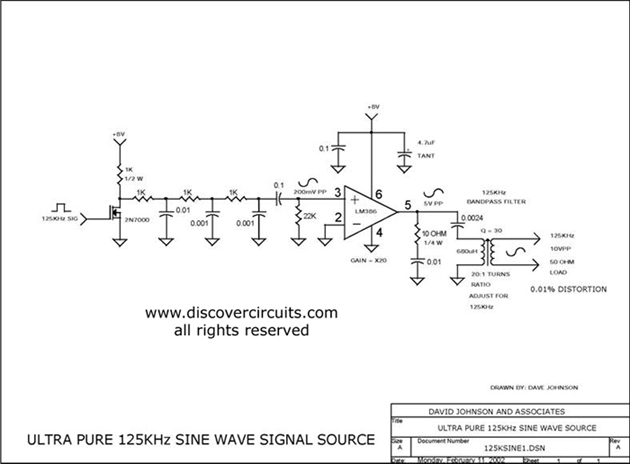
Ultra pure 125 kHz sine wave signal source. For certain RFID systems operating at 125 kHz, a very low distortion signal source is essential. The circuit presented here produces a 10-volt peak-to-peak signal. The ultra pure 125 kHz sine wave...
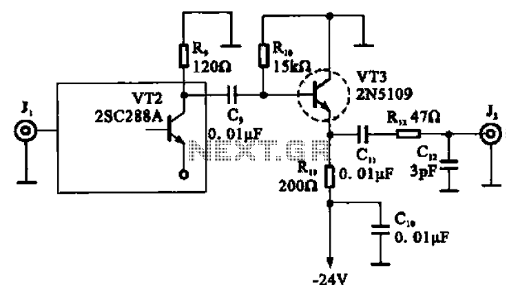
A high-frequency signal is displayed in the output amplifier. The circuit consists of a VI3 common collector amplifier (emitter follower) designed to enhance the child-band. It is a high-frequency amplifier (1-250 MHz) that increases the output voltage and boosts...