
Soil moisture meter circuit
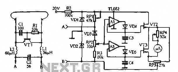
The soil moisture meter circuit is designed to measure the volumetric water content in soil, providing valuable data for plant care and irrigation management. The circuit typically consists of a moisture sensor, an operational amplifier, a microcontroller or analog meter for display, and a power supply.
The moisture sensor is usually a resistive type, where two electrodes are inserted into the soil. The resistance between the electrodes changes with the moisture content; drier soil has higher resistance, while wetter soil exhibits lower resistance. This change in resistance can be converted into a voltage signal using a voltage divider configuration.
The operational amplifier amplifies the voltage signal from the sensor, ensuring that it is within the appropriate range for the microcontroller or display device. If an analog meter is used, the output from the operational amplifier can be directly connected to the meter, providing a visual indication of soil moisture levels.
In more advanced designs, a microcontroller can be programmed to interpret the sensor data and control additional features, such as activating a pump for irrigation when moisture levels fall below a predefined threshold. The microcontroller can also provide a digital readout of the moisture level on an LCD or LED display, allowing for easy monitoring.
Power supply options for the circuit can include batteries or a DC power adapter, depending on the intended application and portability requirements. Proper calibration of the sensor is essential to ensure accurate readings, which may involve testing in soils of varying moisture content.
Overall, this soil moisture meter circuit is an essential tool for gardeners and farmers, helping to optimize water usage and promote healthy plant growth.Soil moisture meter circuit is usefull for monitoring the moisture at your plants. An easy circuit and very usefull.
Related Circuits
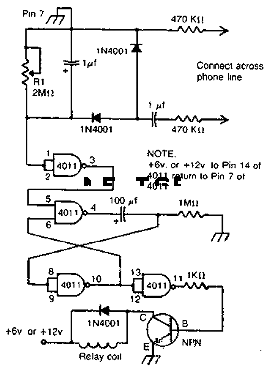
By cross-connecting the telephone ringing circuit, when the phone rings, the circuit activates the relay. It utilizes a delay in contact to drive various devices such as bells, sirens, buzzers, or lights. The telephone ringing circuit is designed to detect...
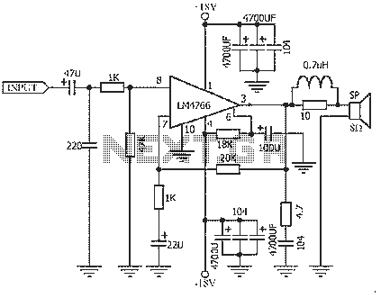
The NS LM4766, launched by a US company, is a two-channel power amplifier integrated circuit. Each channel can output an average power of 40W at an 8-ohm load, with distortion levels lower than 0.1%. It is part of National...
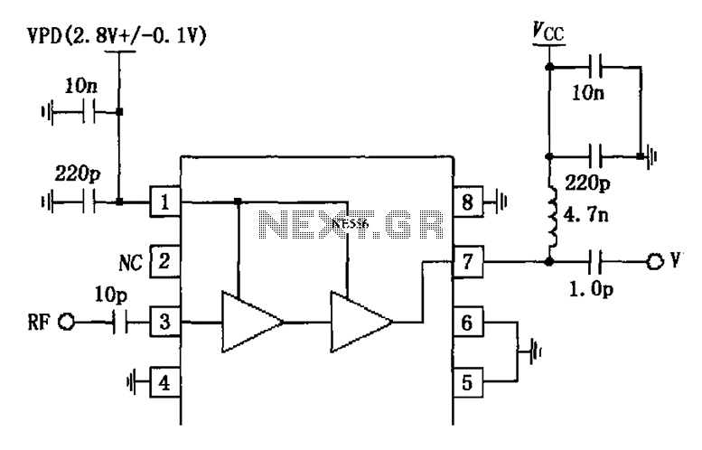
The circuit is constituted by the RF2324 1880MHz internal amplifier collector bias application. A radio frequency (RF) signal enters through input pin 3 and is processed by a preamplifier. The final stage power amplifier output is amplified by 7...
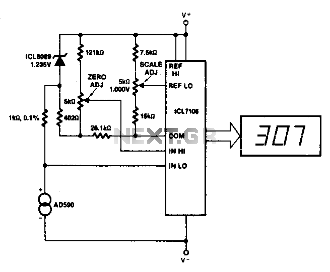
This circuit allows for zero adjustment as well as slope adjustment. The ICL8069 brings the input within the common-mode range, while the 5 kΩ potentiometers trim any offset at 218 K (-55 °C) and set the scale factor. The described...
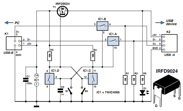
Individuals engaged in the experimentation or development of USB-connected peripheral hardware often find it frustrating to repeatedly disconnect and reconnect the plug to reestablish communication with the PC. This procedure is necessary, for instance, every time the peripheral device...
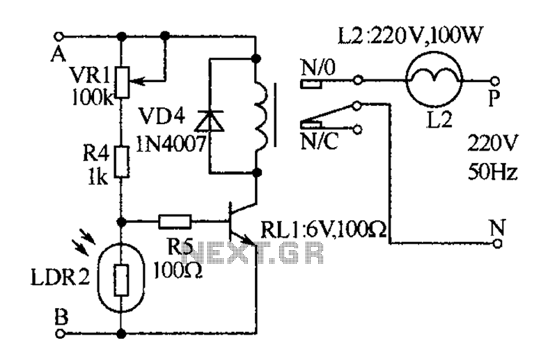
The receiver, as depicted in the figure, assists patients in avoiding missed audio signals during the daytime. The receiver operates independently, and the lighting will automatically turn off. At night, the lighting signal receiver activates simultaneously with the patient's...