
multiplexer with limiter and low pass

The BH1417 Stereo Encoder circuit is designed to effectively encode stereo audio signals for transmission, ensuring high fidelity and minimal interference. The pre-emphasis stage enhances high-frequency sounds, which compensates for the inherent losses that occur during transmission. The limiter stage serves to prevent audio clipping, maintaining a consistent output level and enhancing the overall listening experience.
The low-pass filter is critical in this design, as it attenuates frequencies above 15 kHz, which are unnecessary for audio transmission and can contribute to RF interference. This filtering capability is essential in maintaining signal integrity and ensuring that the transmitted audio remains clear and free of unwanted noise.
The BH1417 IC's specifications allow it to operate efficiently within a supply voltage range of 6 to 15V, making it versatile for various applications. Its low current consumption of approximately 25mA is beneficial for battery-powered devices, extending operational life while maintaining sound quality. The impressive 40dB channel separation ensures that the left and right audio channels are distinctly reproduced, enhancing the stereo experience.
Although the BH1417 is housed in an SOP22 package, which may be less familiar to some engineers compared to DIP packages, its compact size facilitates the design of smaller PCBs. This is particularly advantageous in modern electronics where space is often a constraint.
For oscillator requirements, the use of a 7.68 MHz crystal in place of the specified 7.6 MHz crystal is a practical solution. The slight frequency difference does not adversely affect the encoding process, as confirmed by testing. This flexibility in component selection can simplify sourcing and reduce costs, making the design more accessible.
Overall, the BH1417 Stereo Encoder circuit represents an effective solution for transmitting high-quality stereo audio signals, combining advanced features with practical design considerations.This is a design circuit for stereo encoder. This circuit is using BH1417 Stereo Encoder. This circuit using with pre-emphasis, limiter so that the music can be transmitted at the same audio level, low pass filter that blocks any audio signals above 15 KHz to prevent any RF interference and crystal based stereo encoder for stereo transmission. Thi s is the figure of the circuit. The BH1417 single chip IC can be supplied with 6 - 15V voltage, consumes only around 25mA while providing very sound quality and improved 40dB channel separation. The IC is only available in SOP22 IC case and this may be an inconvenience for some folks. On the other hand, because the chip is smaller than regular DIP-based ICs it is possible to fit the entire stereo coder on a small PCB.
This IC is requires 7. 6MHz crystal oscillator which is pretty hard to find. The good news is that you can use 7. 68 MHz crystal instead. In fact our BH1417 stereo encoder prototype uses 7. 68 MHz crystal. This has absolutely no effect on stereo encoding process, we have tested it and stereo sound is crystal clear. 🔗 External reference
Related Circuits

The operation and circuit diagram of a low-cost amplifier utilizing BC107 and BC148 transistors are explained in detail. The low-cost amplifier circuit employs two types of transistors, BC107 and BC148, which are commonly used for their favorable characteristics in audio...
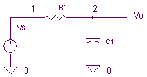
What is the purpose of this circuit? Basically it has two roles: to pass the desired low frequency signals and stop the unwanted high frequency signals. Open the netlist file lpfilter1.cir with your SPICE simulator. Most simulators display the...
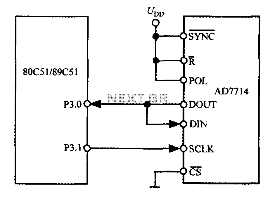
The 3-wire interface to the AD7714 can be utilized with various microcontrollers, including microcontrollers and microprocessors. This 3-wire serial interface is particularly suitable for isolation systems, allowing the use of optical couplers. The interface circuit between the AD7714 and...
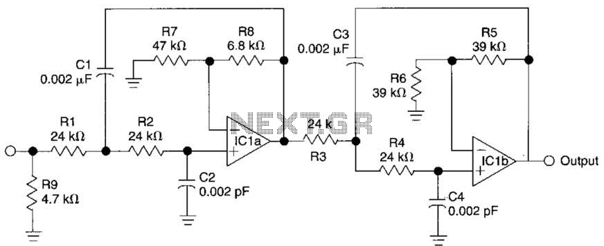
This circuit is a fourth-order low-pass filter designed for operation at kilohertz frequencies. The component values for resistors R1, R2, and capacitors C1, C2, as well as resistors R3, R4 and capacitors C3, C4 can be adjusted for functionality...
Power line fluctuations and cut-offs can damage electrical appliances connected to the line, particularly domestic appliances like refrigerators and air conditioners. When a refrigerator operates on low voltage, excessive current flows through the motor, leading to overheating and potential...
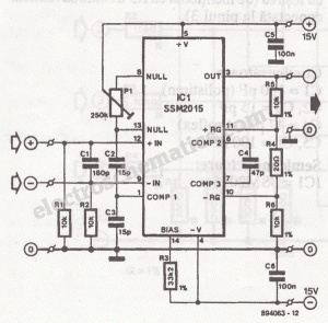
The microphone preamplifier circuit design presented in this schematic utilizes the SSM2015 produced by Precision Monolithics Inc. (PMI), which offers high amplification. The SSM2015 is a low-noise, low-distortion integrated circuit designed specifically for microphone preamplification. It features a differential input...