
Wailing Alarm Siren
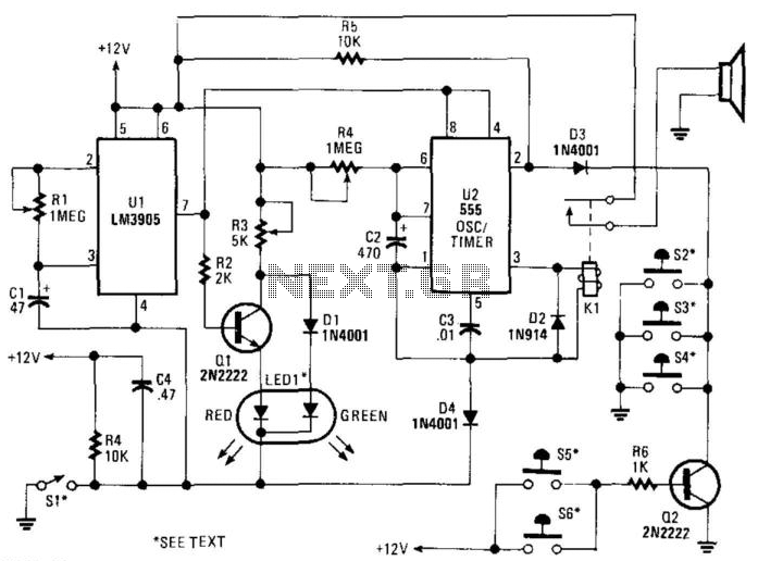
The alarm siren circuit typically consists of an oscillator, a frequency modulator, and a power amplifier. The oscillator generates a square wave signal that is used to create the desired frequency sweep. This signal is fed into a frequency modulator, which alters the frequency of the oscillator output over a specified period, producing the characteristic warbling sound.
The frequency sweep is accomplished by varying the control voltage applied to the modulator, which can be achieved using a capacitor and a resistor in an RC timing circuit. The time constant of this RC network determines the rate of frequency change. For this specific circuit, the upward frequency sweep lasts for 3 seconds, followed by a downward sweep for another 3 seconds, creating a complete cycle of 6 seconds.
To amplify the output sound, a power amplifier is connected to the modulated signal. This amplifier boosts the signal strength to drive a loudspeaker or siren, ensuring that the sound produced is loud enough to serve its intended purpose, such as alerting individuals in an emergency situation.
The design may also incorporate a power supply circuit, which can be powered by batteries or an AC source, ensuring that the circuit operates reliably under various conditions. Additional components such as diodes may be included for protection against reverse polarity, and capacitors can be used for filtering to ensure a clean output signal.
Overall, this alarm siren circuit is an effective solution for producing a recognizable alert sound, utilizing simple electronic components to achieve the desired acoustic effect.This alarm siren circuit give continuous frequency sweep, a warbling sound. The warbling period is about 6 seconds, 3 seconds for frequency sweeping up and 3.. 🔗 External reference
Related Circuits
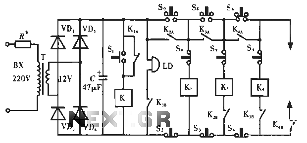
The circuit operates as illustrated in Figure 5-2a. It includes an alarm switch (S). When switch S is pressed, relay K is activated, which closes two normally open contacts. This action triggers the alarm bells. The alarm continues to...
SI is an external key switch. The alarm allows a delay of 0 to 45 seconds after SI is operated before the circuit is armed. During this period, LED1 lights up green. After this delay, LED1 lights red, indicating...
This simple circuit is sure to have the police beating a path to your door - however, it has the added advantage of alerting you to their presence even before their footsteps fall on the doormat. The circuit transmits...
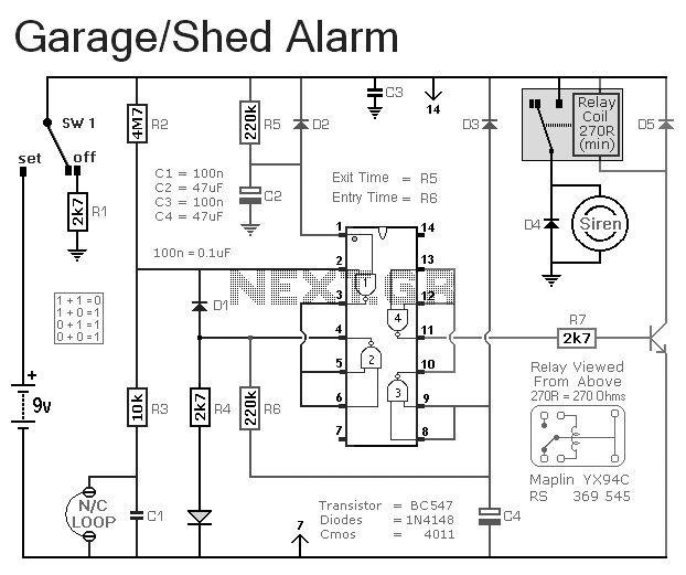
This is a simple single-zone burglar alarm circuit. Its features include automatic exit and entry delays. It is designed to be used with the usual types of normally-closed input devices such as magnetic reed contacts, micro switches, foil tape,...
This circuit is intended for children fun, and can be installed on bicycles, battery powered cars and motorcycles, but also on models and various games and toys. With SW1 positioned as shown in the circuit diagram, the typical dual-tone...
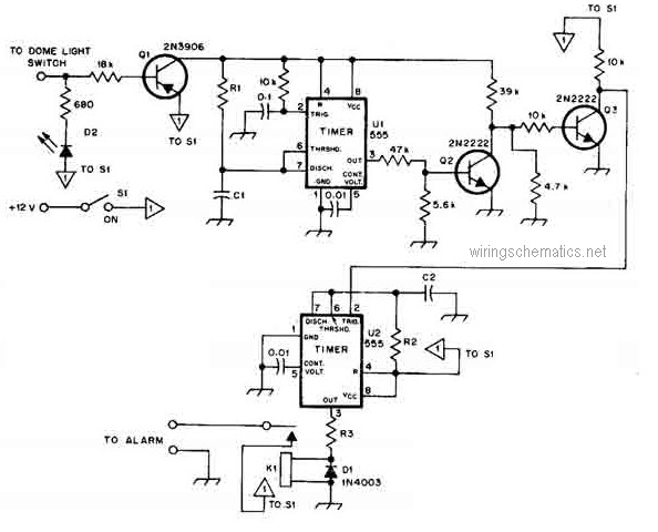
This circuit diagram represents a smart car alarm timer. This design is more advanced compared to traditional car alarm systems. When activated, the alarm remains active for 80 seconds, following an initial delay of 15 seconds. The smart car alarm...