
Music Equalizer Display Circuit

The music equalizer display schematic is designed to visually represent audio signals through an array of LEDs, providing a dynamic visual experience in synchronization with sound. The schematic incorporates a microcontroller, typically a PIC, which processes the incoming audio signal from a laptop or similar audio source. The audio signal is fed into the microcontroller's analog input pin, RA0/AN0, where it undergoes analog-to-digital conversion.
To facilitate both audio output and signal visualization, a speaker is connected in parallel with the input. This configuration allows the user to hear the audio while the microcontroller analyzes the signal for LED output. The use of a voltage divider formed by two 1k resistors is crucial for adjusting the reference voltage of the analog-to-digital converter. By setting the reference voltage to 2.5V, the system can more accurately process low-voltage audio signals, enhancing the LED display's responsiveness and accuracy.
The output from the microcontroller is directed to three designated ports, which control the LED array. The update rate of 0.2 milliseconds ensures that the LEDs change in response to the audio input in near real-time. However, consideration for a slightly slower update rate of 1 millisecond may be beneficial for visual clarity, allowing the LEDs to fully illuminate before the next update cycle.
The power supply for the circuit is a critical aspect, as the direct connection of a battery to the PIC may lead to inefficiencies due to the unavailability of standard 5V batteries. The circuit is designed to accommodate a voltage input range of 4.8V to 5.5V, providing flexibility in power supply options. The choice of a 20 MHz clock rate is based on available components, although the lack of capacitors on the crystal connections may affect stability. Nonetheless, the simplicity of the design mitigates the impact of these omissions, allowing for effective operation of the music equalizer display circuit.The music equalizer display schematic is not a very difficult one to build. I managed to fit it all on a nice little breadboard. You will need all the parts listed out on the previous page to put it together. It is quite wire-intensive so make sure you have plenty of extra wire handy. The audio signal that the laptop generates will be input into RA0/AN0. In order to be able to hear the sound as well as to see the signal on the led`s we`ll stick a speaker in parallel with the input to the PIC. This will decrease the true voltage of the audio signal that the PIC sees however we`ll deal with this issue in the PICs software.
The 2 1k resistors are used to create a voltage divider for the analog to digital converter`s reference voltage. This means we use these two resistors to have the audio signal compared to 2. 5v instead of 5v. The reason we do this is because the audio signal that is input is low voltage and if our reference is closer to it the output to the leds will be far more accurate & entertaining to watch.
After all the analog to digital conversions are complete these three ports will be used to output the result. It is updated once every 0. 2 mS which is right on the border of too fast. An update rate of 1mS might be better. The reason for the update delay is so that there is enough time for the leds to light up. The power circuit design for this circuit is simply hooking the battery up to the PIC. This is a bad design as 5v batteries are not common, however the circuit is simple enough where 4. 8-5. 5v input is also acceptable. The 20 MHz clock rate was chosen at random (spare clock/crystal I found laying around). Again the clock input is of a bad design because there aren`t any caps off of each side of the crystal but since the circuit is so simple these advanced design techniques are not crucial.
🔗 External reference
Related Circuits
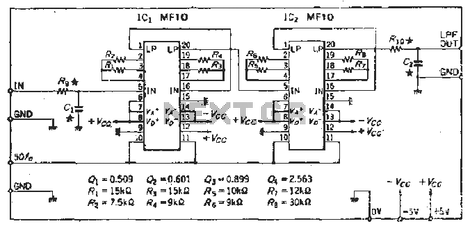
To create a Butterworth low-pass filter with a 12 dB/octave roll-off, four second-order (12 dB/oct) filter blocks are connected in series. This configuration is intended to achieve flat response characteristics across the frequency spectrum. The values for each stage...
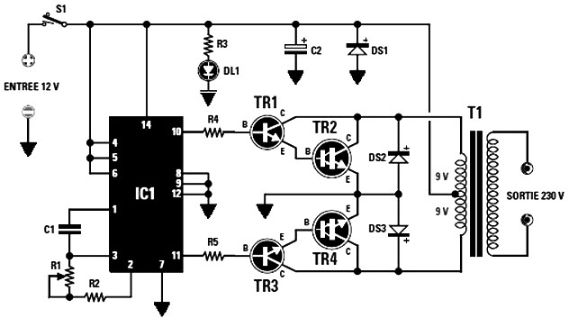
The final power transistors TR2 and TR4 must be mounted on appropriately sized heatsinks to prevent overheating. Suitable transistor options include MJ4033, MJ3007, or any other NPN type. The maximum power output is dependent on the transformer T1's core...
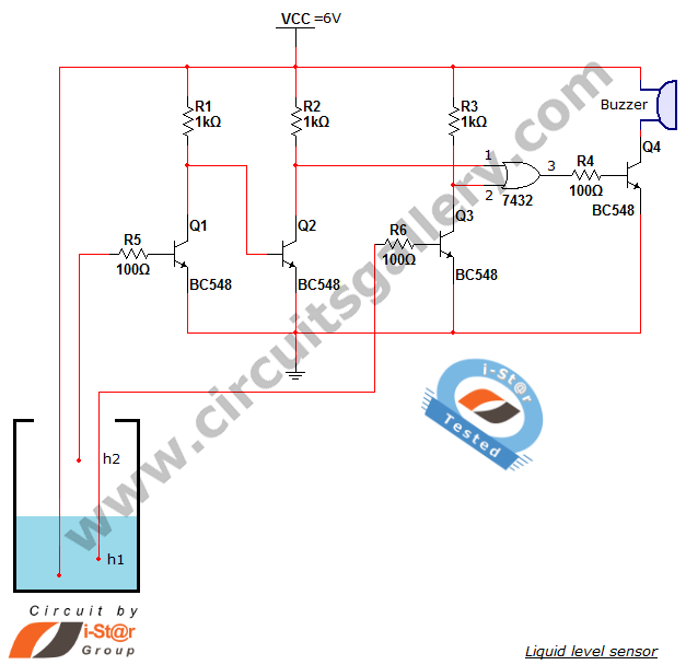
A variety of small electronic projects related to water level sensors have been posted in the Circuits Gallery. This particular project is designed for school students to detect the water level within a water tank or any other water...
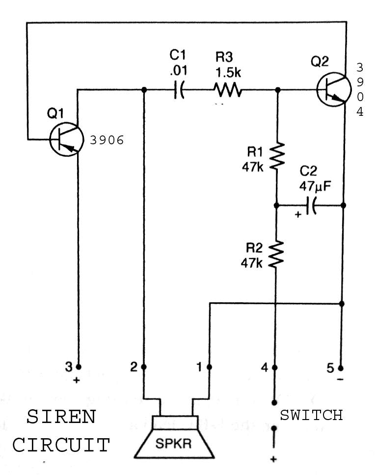
3904 3906 Siren Circuit. The circuit generates a wailing siren sound when the switch is activated. The 3904 3906 Siren Circuit is designed to produce a distinctive wailing sound, commonly used in alarm systems and signaling devices. The circuit utilizes...
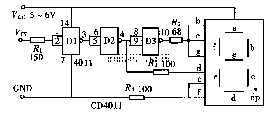
The door circuit logic pen text display can take many forms, utilizing various logic gates such as inverters, NAND gates, NOR gates, and others. A logical pen, exemplified by the NAND gate CD4011, can be used in conjunction with...
Almost all 24V power systems in trucks, 4WDs, RVs, boats, etc., utilize two series-connected 12V lead-acid batteries. The charging system can only sustain the total voltage of the individual batteries. If one battery is failing, this circuit will illuminate...