
NPN BJT in saturation base voltage irrelevant
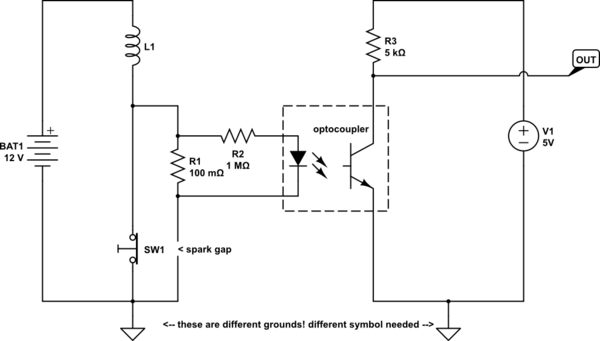
The proposed circuit involves utilizing an NPN BJT to detect the firing of an automotive ignition coil by pulling a logic line low. The ignition coil generates high voltage, and the circuit must be designed to handle this safely. The negative terminal of the ignition coil is connected to the base of the NPN transistor through a current-limiting resistor. This resistor is crucial as it protects the transistor from excessive base current when the coil fires. The emitter of the BJT is connected directly to ground, allowing the transistor to turn on when the base is pulled high.
To ensure proper operation, the circuit must account for the high voltage generated by the ignition coil. When the ignition coil fires, the negative terminal can reach voltages around 300V due to the counter-electromotive force (counter-EMF). This high voltage can cause issues if not managed correctly. A voltage divider could be implemented at the base to ensure that the base-emitter voltage remains within safe limits, allowing the transistor to operate effectively without damage.
In addition to the base resistor, it is advisable to include a resistor from the base to ground. This resistor serves to limit the base current and ensures that the transistor does not enter saturation prematurely, which could happen if the primary current from the coil is too high. The suggested value of around 100 ohms or less is a starting point, allowing for adjustments based on the specific characteristics of the ignition coil and the BJT used.
The switch (S1) in the schematic represents the mechanism that triggers the ignition coil. When S1 opens, the primary current from the coil will attempt to flow into the base of the transistor. Since the BJT is a current-driven device, it requires minimal base current (typically 1-2 mA) to saturate, while the primary current may be significantly higher, potentially leading to damage if not limited. The design needs to ensure that the base current is controlled, allowing the circuit to function as intended without compromising the integrity of the BJT.
In conclusion, careful consideration of component values and circuit design is essential to create a reliable circuit that effectively pulls a logic line low when the ignition coil fires. Properly managing the high voltage and current levels will ensure the circuit operates safely and effectively.Build as simple a circuit as possible that will pull a logic line low every time an automotive ignition coil `fires`. My first inclination is to simply attach the `negative` terminal of the coil to the base of of an NPN BJT through a current-limiting resistor, with the emitter tied directly to ground.
So there would be 5V on the coll ector and roughly 300V on the base resistor when being triggered. Somehow, though, I feel like I`m missing something fundamental that won`t let this work. Perhaps it`s just me being spooked by the `high` voltage. I suppose I could use a voltage divider at the base, but I still feel like I`m missing something. Looking for confirmation regarding the proposed functionality, or of my idiocy. Thanks. Edit: I don`t intend to pass any current through the transistor, besides what little is required by the device itself. The idea is that the transistor will go into saturation when the ground is removed from the coil (when the counter-EMF brings the coil`s `negative` terminal up to around 300 volts).
Here`s a (rather amateurish) schematic of what I`m thinking: Switch `S1` in that schematic is just a placeholder for the IGBT/Points triggering the ignition coil. Sorry again for the confusion, and thank you, everyone, for all the replies! Your description sounds like you are trying to pass the primary coil current through the base-emitter junction via a resistor that would severely limit the primary current and would not work.
Please post a circuit diagram. JIm Dearden May 22 `13 at 6:28 A BJT is in essence a current driven device, hence base voltage is, for most purposes, irrelevant, as long as the actual voltage expressed on the base-emitter junction is within device ratings. However, without a schematic, determining whether the approach is feasible or practical, is very difficult.
Please upload a schematic on any public image hosting site, and provide the link as an edit to the question: Someone with edit permissions will incorporate the diagram into your question. Anindo Ghosh May 22 `13 at 7:22 I didn`t see the schematic when I wrote my response. What you have depicted looks like it ought to work, but consider that when S1 opens, whatever the primary current happens to be, that will all be driven into the base of the transistor.
The transistor probably won`t need more than 1 or 2 mA to saturate, and for any decent output from the coil, the primary current is likely up in the hundreds of mA, maybe even an amp or more. This will be hard on the transistor. Suggest adding a resistor from base to ground. JustJeff May 24 `13 at 10:12 The value depends on the primary coil current at S1 opening and the transistor, but I`d guess it would be 100 ohms or less.
Assuming this is a one-off experiment, you could start low and work upward. JustJeff May 24 `13 at 10:15 🔗 External reference
Related Circuits
This circuit monitors battery voltage and features a three-LED display. By connecting this circuit to the battery of a vehicle, users can easily determine the approximate voltage at a glance. The battery voltage monitoring circuit utilizes a simple yet effective...
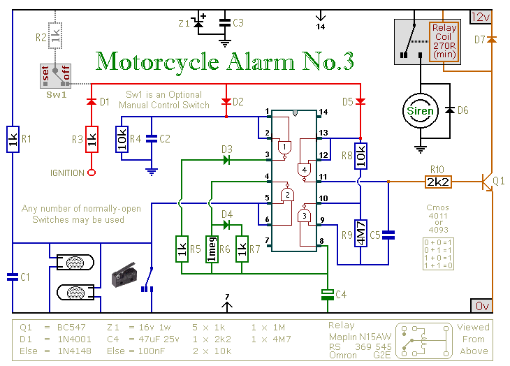
This circuit provides an intermittent siren output with an automatic reset feature. It can be operated manually through a key-switch or a hidden switch, and it can also be configured to activate automatically when the ignition is turned off....
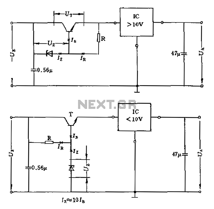
The voltage equation Ue = Ut + Ur + Ua indicates that the transistor voltage Ut will determine the maximum output voltage Ua. Additionally, Ur must be 2V. The voltage regulator's voltage value depends on the selection of Uz....
The following circuit illustrates a simple stepper motor controller circuit diagram. This circuit is based on the 7404 integrated circuit. Features include suitable heat dissipation. The simple stepper motor controller circuit utilizes the 7404 hex inverter IC to control the...
The high and low voltage cut-off with delay and alarm circuit, along with its circuit diagram, is explained in this post. The high and low voltage cut-off circuit is designed to protect electrical devices from damage caused by excessive voltage...
The circuit possesses significant educational value. It has not been tested. Users can simulate and test it or construct it to evaluate its performance. The circuit functions as a simple analog-to-digital converter. Optocouplers can be used in place of...
Warning: include(partials/cookie-banner.php): Failed to open stream: Permission denied in /var/www/html/nextgr/view-circuit.php on line 713
Warning: include(): Failed opening 'partials/cookie-banner.php' for inclusion (include_path='.:/usr/share/php') in /var/www/html/nextgr/view-circuit.php on line 713