
Two sirens sound with ic 555
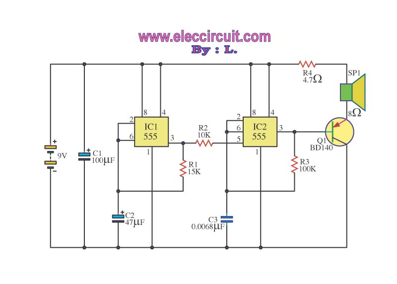
The circuit is designed to operate in three distinct frequency ranges, enabling a versatile audio output. The first part, the low-frequency production, utilizes IC1 configured as an astable multivibrator. The frequency of oscillation is primarily influenced by the values of R1 and C2, where R1 is a resistor that defines the charge and discharge time of C2, a capacitor. The output from pin 3 of IC1 is a square wave signal with a frequency close to 1 Hz, which is suitable for generating low-frequency tones.
The second part of the circuit involves IC2, which is responsible for producing high-frequency signals. The input to IC2 at pin 5 is derived from the low-frequency output of IC1 after passing through resistor R2, which conditions the signal for appropriate amplitude and impedance. The frequency of IC2 is adjustable through the selection of R3 and C3. C3 plays a crucial role in determining the output frequency; a smaller capacitance results in a higher frequency output, which translates to a treble tone.
The final part of the circuit is the amplification stage, which utilizes transistor Q1. The output from three specific legs of IC2 is fed into the base of Q1. This configuration allows Q1 to act as a signal amplifier, increasing the power of the audio signal to a level sufficient to drive speakers effectively. The design ensures that the audio output can cover a wide range of frequencies, providing a rich and dynamic sound experience. Proper selection of components is essential to achieve the desired audio characteristics and ensure compatibility with the connected speakers.Operation of the circuit. Circuit is divided into three parts: low frequency production. The manufacturing high frequency and extension of production low frequency is obtained from IC1 connected to astable multi vibrator circuit frequency is set by R1, C2 frequencies that are coming out of pin 3 is about 1 Hz through R2 to be good 5. of IC2, a div ision produce high-frequency input at Pin 5 will tone the origin of oscillator IC2 is the ripple of voltage from the output of IC1 frequency of IC2 is being set by R3, C3, which, if C3 value. will be very low tone if C3 is less treble The output will have to stand out in three legs of IC2 to stimulate B of Q1 to amplify signals that drive speakers.
Disclaimer All files are found using legitimate search engine techniques. This site does not and will not condone hacking into sites to create the links it list. We will and do assume that all links found on the search engines we use are obtained in a legal manner and the webmasters are aware of the links listed on the search engines. If you find a URL that belongs to you, and you did not realize that it was "open to the public", please use the report button to notify the blogmaster of your request to remove it or it will remove within 24 hours.
This is not an invitation for webblog haters to spam with requests to remove content they feel that is objectionable and or unacceptable. Proof of URL ownership is required. NOTICE: This Blog Has Already Been Reviewed And Accepted By Blogger. com 🔗 External reference
Related Circuits
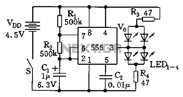
The circuit consists of a 555 timer and a light-emitting diode (LED) array. The 555 timer, along with resistors R1, R2, and capacitor C1, forms an astable multivibrator configuration. The oscillation frequency is calculated using the formula f =...
The bat ultrasounds are picked up by the microphone SPKR1 and go through two stages of amplification at Q1 and Q2. Separately, a tunable (R12) single frequency is produced by the LM567 oscillator U1. The LM567 is a tone...
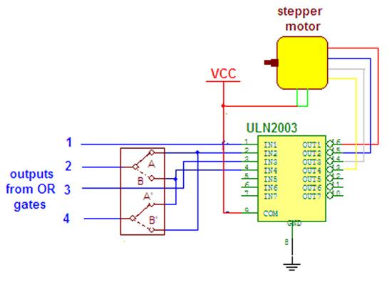
Wireless stepper motor speed control project using a laser and IC555. This project provides insights into the fundamentals and circuit construction for controlling the speed of a wireless stepper motor utilizing a laser and the IC 555 timer. The project...
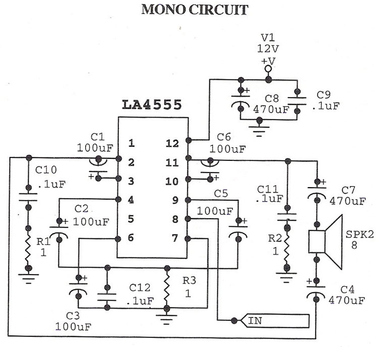
The LA4555 audio amplifier schematic includes both stereo and mono configurations. The LA4555 is primarily designed as a stereo amplifier, delivering 2.3 watts of power into 4-ohm speakers. The LA4555 audio amplifier is an integrated circuit designed for audio amplification...
This circuit illustrates a Wiper Speed Control Circuit Diagram. The sweeping rate of the wiper can vary from once per second to once every ten seconds. The Wiper Speed Control Circuit is designed to regulate the speed of windshield wipers...

The circuit utilizes a 555 timer IC to create a lighting group delay effect, as illustrated in Figure 2-46. It consists of the 555 IC along with a resistor and capacitor configuration that establishes the delay. The circuit remains...