
One-Shot Multivibrator
The one-shot multivibrator, also known as a monostable multivibrator, is a crucial component in various electronic applications. It operates by producing a single output pulse of a predetermined duration in response to a triggering event. The circuit typically consists of a timing resistor and a timing capacitor, which together define the width of the output pulse.
When the input signal transitions from low to high (or vice versa, depending on the configuration), the multivibrator is triggered. The timing capacitor begins to charge through the resistor, and the voltage across the capacitor rises until it reaches a specified threshold. Once this threshold is reached, the output switches from low to high, generating the fixed-width pulse. The duration of this pulse is determined by the RC time constant, which is calculated as T = 1.1 * R * C, where T is the pulse width, R is the resistance, and C is the capacitance.
The output pulse will remain high for the duration defined by the RC components, after which it returns to its low state, regardless of the input signal's duration. This characteristic makes the one-shot multivibrator particularly useful in applications such as pulse width modulation, timers, and signal conditioning.
In practical implementations, one-shot multivibrators can be constructed using discrete components such as transistors, resistors, and capacitors, or they can be realized using integrated circuits like the 555 timer. The choice of components and configuration will depend on the specific requirements of the application, including the desired pulse width, voltage levels, and load characteristics.A one shot multivibrator generate a fixed width pulse at the output when the input is triggered. This fixed width output should be consistent, regardless the.. 🔗 External reference
Related Circuits
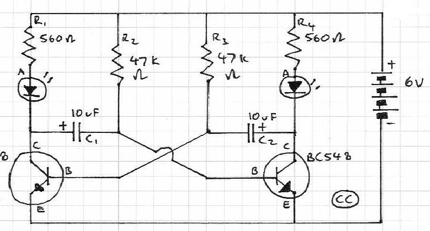
The schematic for a monostable multivibrator is shown in figure 3-11. Like the astable multivibrator, one transistor conducts and the other cuts off when the circuit is energized. More: Recall that when the astable multivibrator was first energized, it...
Blinks 2 LEDs in sequence. An explanation of its operation is requested. It is understood that a capacitor charges, causing the LED to turn off, and when it discharges, the LED turns on. However, clarification on the purpose of...
Engineer Radu Preda from Romania has developed two energy-saving lighting circuits designed to control the duration that lights are activated, ultimately aiming to reduce electricity expenses. The first circuit utilizes a relay, while the second employs an optoisolator triac...
The monostable flip-flop is an electronic circuit that is used to produce a single pulse each time it is triggered. Sometimes, this circuit is referred to as a "one-shot." The monostable flip-flop operates in two states: a stable state and...
In a previous chapter, the use of a transistor as an electronic switch was discussed. This chapter will explore how one transistor can switch another. The diagram illustrates a pair of cross-coupled transistors. The input push buttons of the...
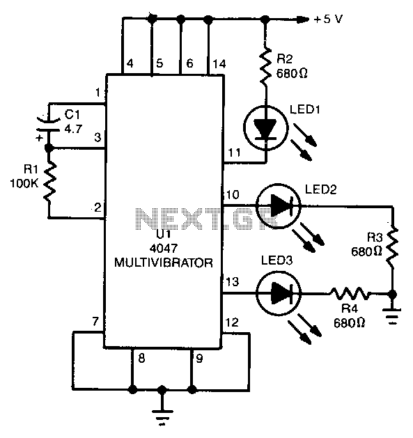
The 4047 is configured as a free-running astable multivibrator (oscillator) circuit. This configuration offers three different outputs. The output pulses at the Q and Q output (pins 10 and 11, respectively) are the same as in the previous two...