
one wire keypad with PIC16F88
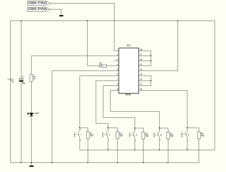
The described project involves the development of a versatile keypad interface that can be utilized in various electronic applications, particularly where user input is required. The circuit is designed to accommodate between 4 to 12 push buttons, connecting them through a single wire alongside a ground connection. This configuration allows for the use of a compact microcontroller, such as an 8-pin variant, making it suitable for projects with limited I/O resources.
The circuit features a setup mode that enables users to adjust the key output rate, which is stored in the microcontroller's memory. This capability is essential for tailoring the response speed of the keypad to specific application needs. To configure the device, a terminal program on a PC is recommended, set to 9600 baud rate, no parity, 8 data bits, and 1 stop bit. This ensures proper communication between the keypad interface and the receiving microcontroller or PC terminal.
Entering setup mode requires pressing and holding the S4 button during power-up. Once activated, the LED indicator will flash, signaling that the user can modify the output rate. The S1 button increases the rate, while the S2 button decreases it, with adjustable settings ranging from a minimum of 10 milliseconds to a maximum of 2550 milliseconds. Each button press adjusts the rate by 5 milliseconds. The S3 button serves as a testing mechanism, displaying the current rate on the LED and through RS232 communication for verification purposes. After adjustments, the S4 button saves the configuration and transitions the circuit into normal operational mode, where pressing any button will flash the LED and transmit the corresponding button number via RS232.
The practical assembly of the circuit can be achieved on a breadboard, utilizing the minimum setup of 4 buttons connected directly to a PC's RS232 port. While the circuit typically operates without a level converter such as the MAX232, it is acknowledged that certain scenarios may necessitate its use to ensure signal integrity. Initial tests may reveal rapid output responses, prompting users to enter setup mode for rate adjustments. After fine-tuning to an appropriate response time, the interface can effectively relay input signals to applications or games through RS232 to keyboard software, converting button presses into keystrokes for enhanced user interaction.This project can be used for many different purposes. Probably the most used application would be to interface to any electronic project that requires a keypad. There are several ready made keypads on the market, but those work with matrix connections and require 7 pins for a 12 button pad.
For new programmers, matrix keypads can be a bit tricky to program. My circuit can use from 4 up to 12 push buttons with only one wire connection ( plus ground pin ) making possible to use a small microcontroller like an 8 pin to use this keypad. It's also built in a setup mode where it's possible to change the key output rate. This setting is saved in the microcontroller's memory. Another use for this is to, for example, connect to the computer and use it to control applications or even games. For the first time I recommend to connect it to any pc and using the terminal program select 9600 Baud, no parity, 8 for byte size and 1 stop bit.
These are the settings for both pc terminal or receiver microcontroller. To enter the Setup mode the S4 button should be pressed and held when turning the power on. The led starts to flash and S1 is used to increase the rate while S2 is used to decrease the rate. The minimum rate is 10ms and the maximum rate is 2550ms. It will increase/decrease 5ms each button press. Pressing and holding S3 will test the setting and will display the rate speed both on led and RS232. Button S4 will save the setting into microcontroller's memory, exit the setup mode and enter the normal mode. In normal mode, when pressing one of the buttons it will flash the led and output the corresponding button number via RS232.
I've assembled the minimum button setup ( 4 buttons ) on a breadboard and connected directly to my PC RS232 port. I didn't use any level converter, such a max232, because it normally works very well without it. In some cases it's required to have the level converter. Turned the power on and pushed the buttons. The output was too fast so I turned the power off. I turned on the power again but this time i entered into setup mode. Increased the rate to 200ms and saved the setting. Tested again and now I get a good response. Using any RS232 to keyboard software it's possible to assign the input signals and convert them to keystrokes.
🔗 External reference
Related Circuits

The circuit operates with VT3 and associated components arranged as a common-base capacitance feedback oscillation circuit. The oscillation frequency is set by capacitors C8, C9, and inductor L1. VT2 serves as a voltage amplification stage that reinjects the audio...

This interface is needed to connect the phone to a PC, because the PC's serial port works with voltage levels between -12 and 12V (RS232 protocol) and the phone operates between 0 and 5V (TTL protocol). Don't even think...
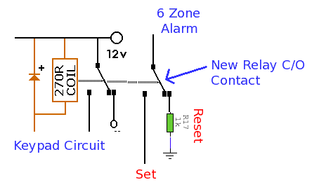
This alarm system features six independent zones, one timed entry/exit zone, a seven-segment LED display, and a test or walkthrough capability. It is designed for use in small office or home environments and can be adapted to utilize a...

The circuit illustrated in Figure 3-76 employs two time relays, KTi and KTz, to manage the operation and downtime of a motor. The circuit utilizes two time relays to provide precise control over the motor's operational cycles. Relay KTi is...

The circuit presented here represents one half of a device that is highly useful for tracing electrical wiring paths in buildings or locating breaks in wires. This system is based on equipment commonly used by technicians in telephone exchanges....

A schematic diagram is a layout of symbols and connections representing every electronic component in a circuit, serving as a guide to understanding how the circuit functions. Learning to read these diagrams may initially seem challenging, but it is...