
Temperature To Frequency Converter Circuit
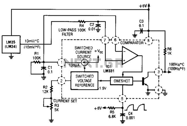
The circuit employs an LM34 or LM35 temperature sensor, which is designed to produce an output voltage that varies linearly with temperature. The key feature of this design is that it converts the temperature measurement into a frequency signal. This frequency output can be directly related to the temperature value, making it suitable for various applications where temperature monitoring is essential.
The reference current, set by resistor R3, plays a critical role in determining the accuracy and stability of the frequency output. By selecting the appropriate value for R3, the desired reference current can be achieved, which in turn influences the frequency range produced by the LM34 or LM35. The output frequency can be calibrated to correspond to specific temperature ranges, allowing for precise temperature readings.
The generated frequency can be interfaced with various devices. For instance, a frequency counter can be connected to measure the output frequency directly, providing a digital readout of the temperature. Alternatively, the output can drive a display, such as an LCD or LED display, which can visually represent the temperature in real-time. Furthermore, this frequency output can be integrated into more complex systems, such as microcontroller-based applications, where additional processing or data logging may be required.
In summary, this circuit effectively transforms temperature readings into a frequency signal, which can be utilized in multiple applications for temperature indication and monitoring. The choice of components, particularly the LM34 or LM35 and the configuration of R3, is vital for achieving the desired performance and accuracy in temperature measurement. In this circuit an LM34 or LM35 produces a frequency proportional to temperature. Reference current (138 ) is set via R3. The output can be used to drive a display, frequency counter, or other indicating device for temperature readout. 🔗 External reference
Related Circuits
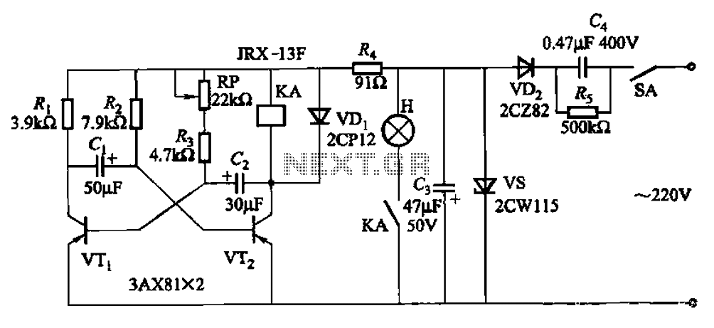
The circuit features a self-excited multivibrator composed of transistors VTi and VTZ. It includes an adjustment potentiometer RP and two RC networks that influence the transistors' parameters, specifically the timing for light activation and deactivation. The described multivibrator circuit utilizes...
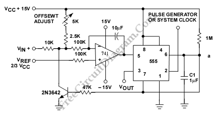
This is a circuit for a Voltage-to-Pulse Duration Converter. The circuit is designed to convert voltage into pulse duration by integrating a timer IC and an operational amplifier (OP Amp). The Voltage-to-Pulse Duration Converter circuit utilizes a timer IC, typically...
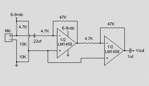
This is a simple preamplifier circuit designed for an electret condenser microphone, utilizing an LM1458 dual op-amp integrated circuit (IC). The circuit amplifies the audio signal from the condenser microphone, allowing it to be used as an input for...
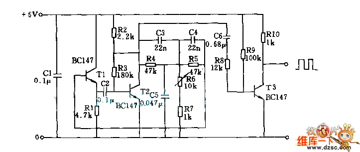
T1 and T2 in the circuit form the inherent oscillator, while T3 serves as the output stage. The network consists of a high-pass filter (C3, C4, R6, and R7) and a low-pass filter. The output from this network is...
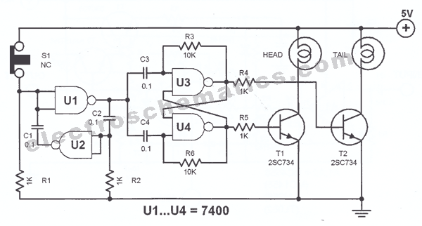
The principle utilized in this electronic head or tail circuit is straightforward: a multivibrator controls a flip-flop. The multivibrator oscillates as long as the button S1 is pressed, while the flip-flop toggles on and off at a frequency of...

This series-feedback configuration of components provides a high input impedance and stable, wide-band gain video amplifier suitable for general-purpose applications. Below is the schematic representation of the circuit. The described video amplifier circuit employs a series-feedback topology, which is instrumental...