
Pocket Theremin on the Cheap

1. Build the circuit. Utilize the Pocket Theremin circuit schematic to assemble the complete dual 555 Timer IC oscillator and frequency divider circuit. Select a pair of CdS photocells from an assortment for experimentation with different sound effects. Ensure the wiring is long enough to comfortably connect all components inside the enclosure.
2. Wire the terminal. Use a 2-position PCB terminal as a connector for the positive (+; red) lead and ground (-; black) lead of the 9-volt battery snap. Connect all +9V circuit connections to one pin of the 2-position PCB terminal and solder them together. Route all GND connections to the other pin and solder the wires accordingly.
3. Deconstruct the box. Disassemble the metal split-level shielded box, removing any plugs, spring-loaded doors, and modular shields that are not desired in the final design.
4. Protect the interior. Insulate the inside of the metal box with tape, plastic tubing, or vinyl strips to prevent any electronic components from shorting out while using the Pocket Theremin.
5. Installation. Place the complete circuit inside the box. Mount the two CdS photocells externally on opposite sides of the box, allowing for better control of the sound effects. Attach the speaker to the front of the box. Connect the red lead from the battery snap to the +9V terminal from step 2, and connect the black lead to the other terminal. Route the 9V battery snap outside the box.
6. Power up. Connect the 9V battery to the battery snap. The Pocket Theremin should immediately begin producing sound. The volume can be adjusted using a 5K potentiometer. If no sound is heard, check for short circuits between components, wiring, and the metal box. If the construction appears correct, try moving the Pocket Theremin to a darker area. In a dimly lit room, the Pocket Theremin should be capable of generating a wide variety of sounds by moving hands over the two CdS photocells to vary the frequency and pitch of the output.
This project not only provides an engaging introduction to electronic circuits but also offers a hands-on experience with sound synthesis and light-sensitive components, making it an excellent educational tool for understanding the principles of electronic music instruments.Even if you`re not familiar with the Theremin itself, it`s very likely you`ve heard its loopy electronic tones before. Remember those spooky sound tracks from 1950s science fiction movies Well, chances are pretty good that those oscillating noises were generated by a Theremin.
Designed by Russian physicist Leon Theremin circa 1919, the two-handed instrument was one of the first ever electronic musical instruments and the first instrument one could play without physically touching it. Thirty years after its invention, the Theremin was popularized by American synthesizer godfather Robert Moog in the 1950s and immortalized in the classic Sci-Fi flick The Day the Earth Stood Still.
A full-fledged Theremin will set you back nearly $400, but with the instructions below, you can build a pocket-sized Theremin-like instrument that won`t break the bank. Unlike the real McCoy which relies on grounded variable capacitance for changing frequency and volume with the wave of a hand, our Pocket Theremin uses variations in light for producing its unearthly vibrato.
Note: Unlike a conventional Theremin which operates on two radio frequency oscillators, this Pocket Theremin consists of an oscillator and frequency divider that are manipulated by changes in light. Be forewarned, the Pocket Theremin is very light sensitive and must be "played" in subdued lighting for achieving the best sound effects.
1. Build the circuit. Use the Pocket Theremin circuit schematic (see below) for building the complete dual 555 Timer IC oscillator and frequency divider circuit. Pick a pair of CdS photocells from the Electronic Goldmine photocell assortment. Try various photocells for different sound effects. Keep all wiring long enough to comfortably string all of the components together inside your box. 2. Wire the terminal. Use the 2-position PCB terminal as a connector for the positive (+; red) lead and ground (-; black) lead of the 9-volt battery snap.
Route all the circuit`s +9V connections to one pin of the 2-position PCB terminal and solder them together. Next, route all of the circuit`s GND connections to the other pin and solder all wires to this pin. 3. Deconstruct the box. Disassemble the metal split-level shielded box. Remove all plugs, spring-loaded doors, and modular shields that you don`t want in your final design. 4. Protect your insides. Insulate the insides of the metal box with tape, plastic tubing, or vinyl strips for preventing any of the electronic components from shorting out while playing your Pocket Theremin.
5. Installation. Install the complete circuit inside the box. Mount the two CdS photocells externally on opposing sides of the box. This placement will help you control the final sound effects with greater independence and dexterity. Now fix the speaker to the front of the box. Screw the red lead from the battery snap into the +9V terminal from Step 2. Screw the snap`s black lead into the other terminal and route the 9V battery snap outside the box. 6. Power up. Connect the 9V battery to the battery snap. The Pocket Theremin should immediately begin to make some noise. You can control the volume of the speaker by adjusting the 5K potentiometer. If you don`t hear anything, check for short circuits between the components, wiring, and metal box. If the circuit construction looks OK, try moving your Pocket Theremin into a darker location. In a slightly darkened room, your Pocket Theremin should be capable of producing a wild, wide variety of sounds.
Just move your hands over the two CdS photocells for varying the frequency and pitch of your Pocket Theremin`s output. 🔗 External reference
Related Circuits
Since the publication of the type 144 theremin project article in September 1998, many of these instruments have been successfully constructed. The 145 theremin retains a heterodyne topology similar to that used in the original instruments by Mr. Theremin,...
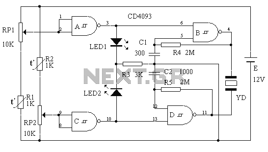
This circuit is a two-way alarm system that utilizes a Schmitt IC, featuring responsive sound and light indicators. It is compact, energy-efficient, and consists of only 13 components, making it a cost-effective solution. The circuit is divided into two...
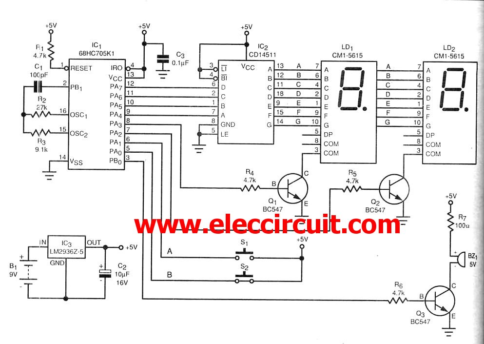
The microcontroller IC is a device that resembles a typical integrated circuit. However, it contains a miniature computer within its architecture. This device can serve as a replacement for transistors. Microcontroller integrated circuits (ICs) are compact, multifunctional devices that integrate...
As part of the National Instruments Tinker, Learn, and Do Engineering with NI myDAQ courseware, the hands-on experiments demonstrate the extensive possibilities of utilizing NI myDAQ hardware. The ten lab experiments encompass various topics, including analog and digital circuits,...
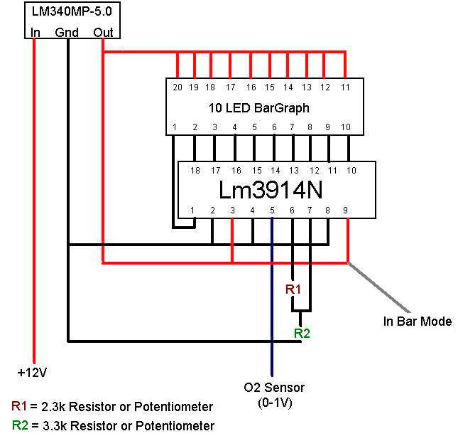
The engine management system monitors its air-fuel ratio using an oxygen sensor (O2) located in the hot exhaust flow, typically positioned before the catalytic converter. All O2 sensors function similarly, with variations including heated sensors or those with multiple...
A more affordable method to create or purchase a device that offers similar functionality. It does not necessarily need to be remote-controlled if it can be programmed to activate at specific times. This description suggests the development of a cost-effective...