
Positive And Negative Voltage Power Supply
This circuit design utilizes a Burr-Brown INA105 difference amplifier, which is known for its high precision and low offset voltage characteristics, making it suitable for applications requiring accurate voltage references. The choice of a potentiometer for gain control provides a user-friendly method for adjusting the output voltage range seamlessly. The configuration allows users to fine-tune the output voltage between the specified limits while maintaining a high degree of accuracy.
The inverting amplifier configuration with a gain of -1.0 V/V ensures that the output voltage is an inverted version of the input voltage, which is particularly useful in applications where signal inversion is necessary. The precision of the circuit is enhanced by the INA105's low noise and high common-mode rejection ratio (CMRR), which minimizes the impact of external noise on the output voltage.
In practical applications, the circuit can be employed in laboratory settings, test equipment, or any scenario where a stable and adjustable voltage reference is required. The ability to achieve exactly 0 V without offset is particularly advantageous in calibration tasks or when interfacing with sensitive electronic components that require precise voltage levels.
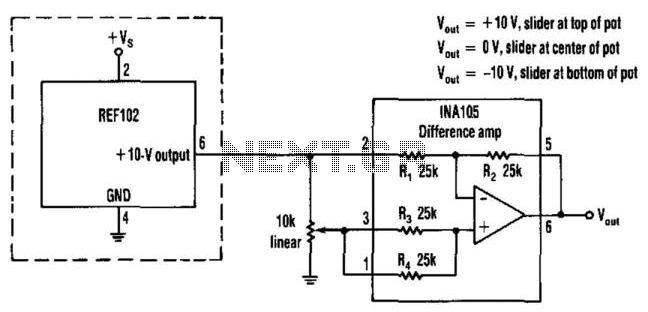
Overall, this precision voltage source circuit exemplifies effective design principles in analog electronics, combining high-performance components with user-adjustable features to meet the demands of various electronic applications. This circuit provides a precision voltage source that can be adjusted through zero to positive a nd negative voltages, which eliminates reversing connections on the power supply. Also, it is possible to get exactly 0 V, without some offset. As to how this circuit works, first consider the -1 V/V to +1 V/V linear gain-control amp (see the figure). A Burr-Brown INA105 difference amp is used in a unity-gain inverting amp configuration. A potentiometer is connected between the input and ground. The pot"s slider is connected to the noninverting input of the unity-gain amp; this input is typically connected to ground.
With the slider at the bottom of the pot, the circuit is a normal-precision unity-gain inverting amp with a gain of -1.0 V/V ± 0.01% maximum. With the slider at the top of the pot, the circuit is a normal-precision voltage follower with a gain of ± 1.0 V/V ± 0.001% maximum.
With the slider in the center, there"s equal positive and negative gain for a net gain of 0 V/V. The accuracy between the top and the bottom will usually be limited by the accuracy of the pot. 🔗 External reference
Related Circuits
This continuity tester circuit allows for the examination of PCB track failures without the need to visually inspect the routing of the tracks, which can often be frustrating. The continuity tester circuit is designed to facilitate the detection of faults...
The VCA project demonstrates the use of the VCA_Setup and VCA_Data components in ADS. These components belong to the ADS behavioral model suite located under the System - Data Models palette. The schematic "Amp_wBothMatches_setup.dsn" is designed to extract circuit-level...
This article is intended for individuals interested in constructing their own car amplifier. The fundamental calculations will be discussed below. Understanding these concepts will enable the construction of a car amplifier independently. The challenge in designing a car power...
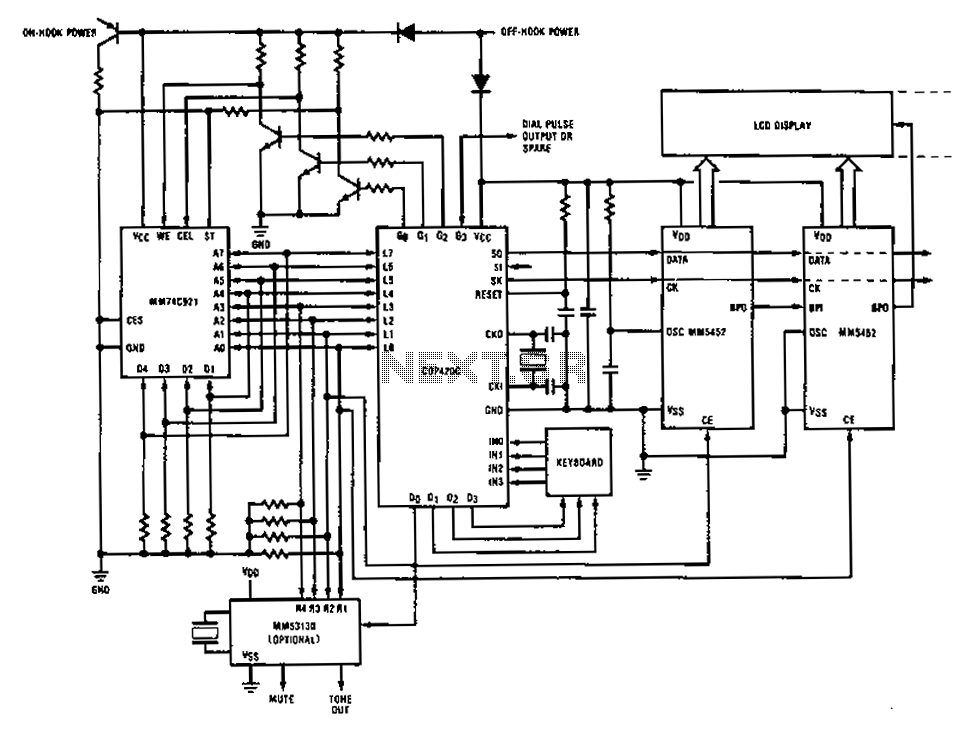
A compilation of dial phone numbers, including 15 commonly used libraries and the dialed number, is stored in standard CMOS RAM. A single-button keypad facilitates the input of a phone number, which can be dialed directly or stored in...
A 50W isolated forward-converter switching supply for telecom applications is described. Most aspects of the design are discussed. The 50W isolated forward-converter switching supply is engineered to meet the specific demands of telecom applications, where reliability and efficiency are paramount....
This chapter presents a variety of circuits for basic power supplies, including both line-powered and inverter types, some of which feature regulators, modulation inputs, and additional functionalities. Several circuits have been reverse-engineered from actual commercial products, and others, designed...