
potential difference between point x and point y
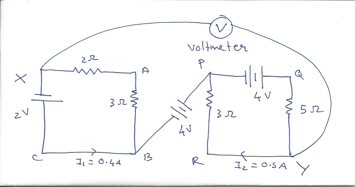
In this scenario, Kirchhoff's Voltage Law (KVL) is applied to analyze the circuit, which consists of two loops and a 4V battery. The voltage law states that the sum of the potential differences (voltage) around any closed loop in a circuit must equal zero. To find the potential drop between the specified points, it is essential to define the reference points clearly.
To calculate the potential difference between points X and Y, first, identify the voltage across the battery. Since the battery has a voltage of 4V and no current flows through it, this voltage remains constant across its terminals. When analyzing the circuit, the potential at point X can be considered as a reference point, typically set to 0V. As one moves from point X to point A, the voltage will increase by the battery's voltage, resulting in a potential at point A of +4V.
Next, to find the potential at point B, it is important to recognize that if there is no current flowing between nodes A and B, the voltage at point B will also be +4V, as there is no voltage drop across an open circuit. Consequently, the potential difference between points A and B is 0V.
Finally, to determine the potential at point Y, one must consider the entire loop. If point Y is connected to the battery and no additional resistances or components are present, it will also be at +4V. Therefore, the potential difference between points B and Y will also be 0V.
In summary, the potential differences can be calculated as follows:
- V(X to A) = 4V
- V(A to B) = 0V
- V(B to Y) = 0V
The overall potential drop between points X and Y can be summarized as being equal to the voltage of the battery, which is 4V, due to the direct connection through the battery. This analysis provides a comprehensive understanding of how to approach the calculation of potential drops in circuits involving multiple loops and components.found the current in both the loops using Kirchhoff`s Voltage law but then I`m confused on the proper method to find the potential drop between the two loops. I suggest you insert two extra points A and B on both ends of the battery (on the bottom right of the left square and the top left of the right square).
Can you calculate the potential difference between X and A, A and B, and finally B and Y Gerben Oct 21 `11 at 12:46 @DavidZaslavsky I found the current in both the loops using Kirchhoff`s Voltage law but then I`m confused on the proper method to find the potential drop between the points X and Y may be can you explain me the procedure as well as find the potential drop between X and Y since there is a 4V battery in middle through which no current flows I wonder how to calculate the potential drop between X and Y+ Praveen Gowda I V Oct 21 `11 at 14:59 @PraveenGowdaIV - There is no complete circuit between nodes A and B, so no current flows. The potential across the battery is. the potential across the battery; 4V. Kevin Vermeer Oct 21 `11 at 15:33 🔗 External reference
Related Circuits

The circuit below is similar to the one above but can be used with a laser pointer to toggle the relay rather than a push button. The IR photo transistor Q1 (Radio Shack 276-145A) or similar is connected to...
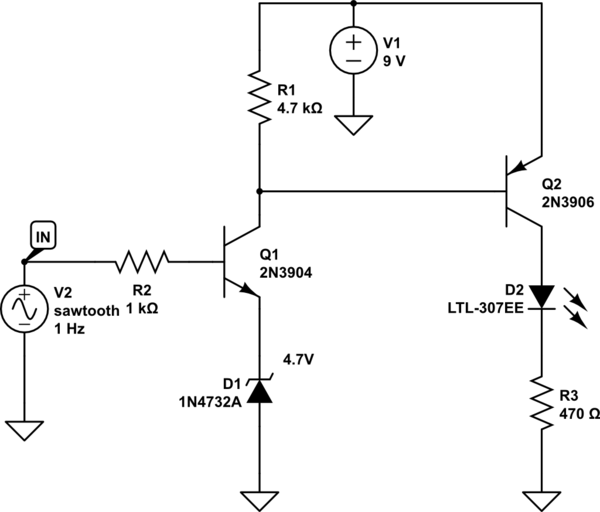
A LED is used to indicate when a DC voltage reaches 5 volts or more. The LED should be fully illuminated at 5 volts and not dim at 4.5 volts or lower. The circuit should be constructed using discrete...
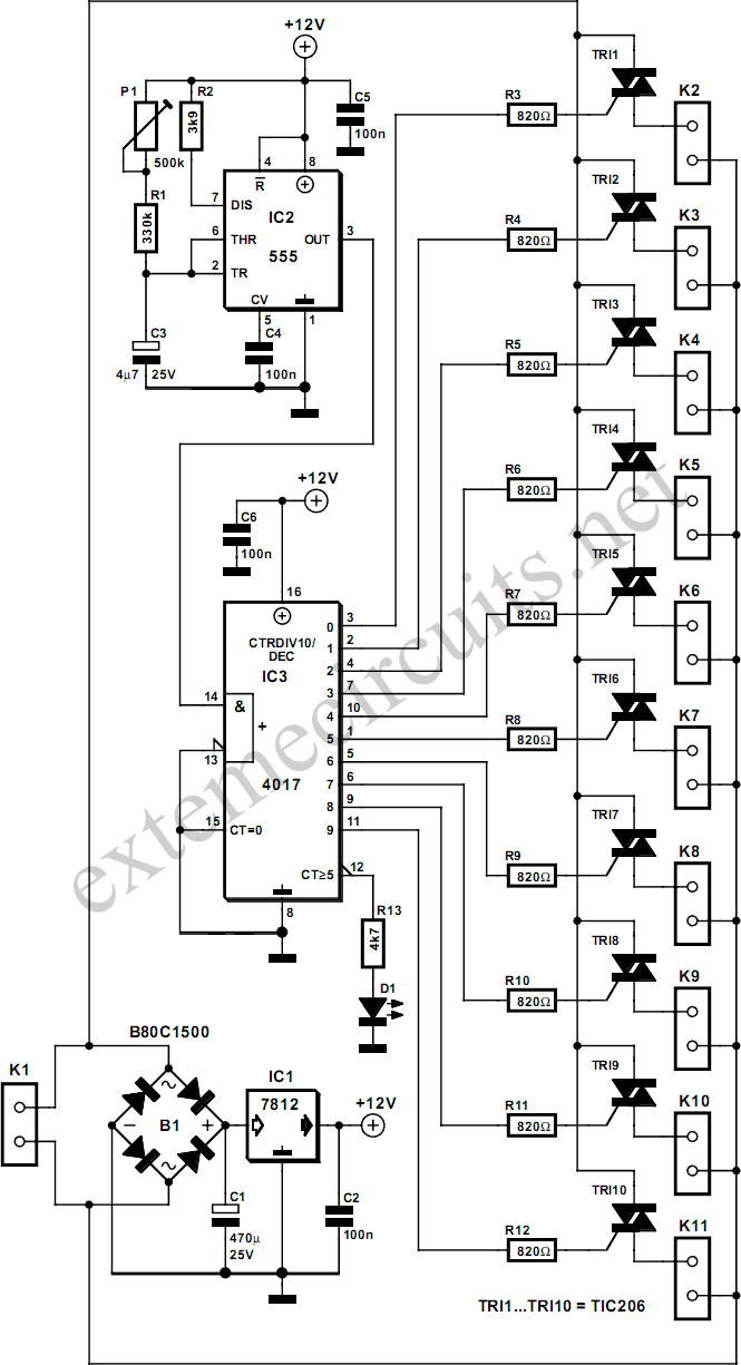
Dedicated model rail enthusiasts using sophisticated train and points controllers often encounter the issue that as their layouts expand and become more intricate, the transformer supplying power to the points does not provide sufficient current to switch multiple points...
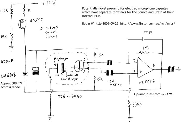
This circuit may be of interest to individuals designing preamplifiers for electret and externally polarized condenser microphones that lack an internal FET. If the noise from a single FET is a limiting factor, utilizing two or four FETs in...
This interface is needed to connect the phone to a PC, because the PC's serial port works with voltage levels between -12 and 12V (RS232 protocol) and the phone operates between 0 and 5V (TTL protocol). Don't even think...
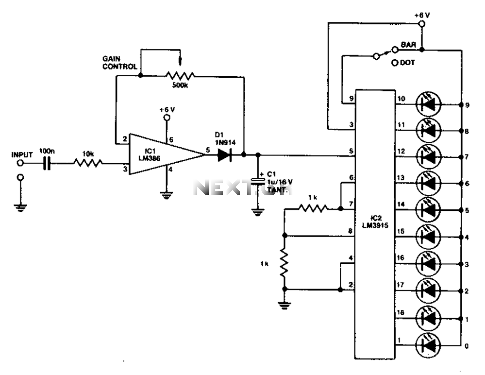
A simple level power meter designed to provide a high-fidelity sound system with a bar or dot matrix display. The green LED display indicates levels from 0 to 7; level 8 is shown in yellow, and level 9 is...