Power Monitor
The objective of this project was to monitor power consumption in a residential setting. In addition to tracking total usage, the goal was to separately monitor and compare the usage of major appliances, such as the water heater, heat pump, and furnace. This necessitated the use of current transformers on individual circuits. Traditional split-core current transformers were prohibitively expensive, costing over $75 each. However, CR Magnetics introduced a new product, the CR3110-3000, which is smaller and more affordable, priced under $13 each. This allowed for the completion of the project with a total cost of approximately $160. The split-core current transformers were clamped around circuit lines in the breaker box, with six 240V circuits and eight 120V circuits monitored. For the 240V circuits, one transformer was placed on one leg, while for the 120V circuits, two circuits were combined in each transformer, resulting in a total of ten current transformers. This setup was compatible with the 11-channel analog-to-digital (A/D) converter, leaving one channel available for monitoring line voltage.
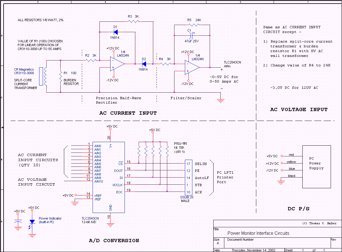
Each current transformer is connected across a burden resistor, producing an AC voltage that is proportional to the AC current. A 100-ohm burden resistor was chosen based on the CR3110-3000 datasheet to maintain the transformer within its linear operating range at currents exceeding 50 amps. The AC voltage is converted to DC through an interface circuit comprising a precision half-wave rectifier followed by a low-pass filter with an 8:1 gain. The output voltage ranges from approximately 0-5V DC for 0-50 Amps AC. The 12-bit A/D converter provides a resolution of approximately 0.01 amps or 1.5W for 120V circuits and 3W for 240V circuits. Line voltage is monitored using a similar interface circuit connected to an 8V AC wall transformer rather than a current transformer and burden resistor. The output from this circuit is approximately 3V DC for 120V AC, with a 12-bit resolution of around 0.05V.
The DC voltage outputs are fed into a TLC2543CN A/D converter, which interfaces with a 486/66 PC via a parallel printer port. The decision to use a PC instead of a microcontroller was based on the availability of an old unit that could power the interface circuits. The 486/66 PC is sufficiently fast for the required processing tasks. A Borland C program running under MS-DOS continuously reads A/D values at a rate of approximately 75 times per second. The data is averaged and scaled to match a handheld meter, and although the PC typically operates "headless" without a monitor or keyboard, it calculates power consumption for each circuit using the formula W = V * A, with the value doubled for 240V circuits. Every five seconds, the computed values are transmitted via the COM1 serial port to a home automation PC, which is a Pentium III running Windows XP. A Visual Basic program on this PC captures the data from the serial port and stores it in an Access database, allowing access from any PC on the home network for graphing and reporting purposes. As more data is collected, it will be compared against the energy usage reported on the electric bill. Additionally, WATTCP was used to add Ethernet support under MS-DOS to the 486/66 PC, enabling data transmission over the network via UDP, which is captured by the home automation PC using Winsock instead of the serial port.
Inside the fuse box, current transformers are attached to individual circuits, with leads terminating at terminal blocks on either side. The 100-ohm burden resistors are soldered to the transformer leads at the terminal blocks to prevent disconnection. It is important to note that a transformer without a burden resistor can induce a dangerously high voltage and may cause arcing. Cat 5 cables run from the terminal blocks to the interface circuitry housed on a panel made of particle board. The setup is designed to ensure efficient monitoring of power consumption across multiple circuits, providing valuable data for energy management.The purpose of this project was to be able to monitor the power consumption at my house. In addition to total usage, I wanted to be able to separately monitor & compare usage of major appliances (water heater, heat pump, furnace, etc. ). This would require current transformers on individual circuits. At $75+ each, most split-core current transforme rs I could find were too expense in the quantity I wanted. Fortunately, CR Magnetics released a new product, CR3110-3000. This split-core is a little too small to monitor the main power lines, but just right for individual circuits. And they are reasonably priced, under $13 each, allowing me to complete this project for about $160. The split-core current transformers are clamped around circuit lines in the breaker box. I have (6) 240V circuits and (8) 120V circuits. For the 240V circuits, I put one transformer on one leg only (more on this below). For the 120V circuits, I doubled them up, putting (2) circuits in each transformer. Thus (10) current transformers where required. This fit with the 11-channel A/D I wanted to use, leaving one channel for monitoring line voltage. Each current transformer is connected across a burden resistors, yielding an AC voltage proportional to the AC current.
The value of the burden resistor (100 ohms) was selected according to the CR3110-3000 datasheet so as to keep the transformer in its linear region of operation to 50+ amps. The AC voltage is then covered to DC via an interface circuit consisting of a precision half-wave rectifier followed by a low-pass filter w/ 8:1 gain (schematic below).
The output is approximately 0-5V DC for 0-50 Amps AC. A 12-bit A/D results in a resolution of ~. 01 amps or 1. 5W for 120V circuits, 3W for 240V. The line voltage is monitored with a similar interface circuit connected to a 8V AC wall transformer instead of a current transformer/burden resistor. The output of this circuit is approximately 3V DC for 120V AC, with 12-bit resolution of ~. 05V. The DC voltages are fed into the A/D (TLC2543CN) which is interfaced to a 486/66 PC via parallel printer port.
I used a PC (vs PIC or other) because I had an old one on hand and could use its P/S to power the interface circuits. The 486/66 is plenty fast enough for the task. A Borland C program running under MS-DOS continuously reads the values from the A/D (approximately 75 times a second).
They are further averaged and scaled (to match hand held meter), and then displayed (though normally this PC is "headless" - ran without monitor or keyboard). The C program also calculates the power for each circuit, W = V * A. This is doubled for 240V circuits (more below). Every 5 seconds, the values are transmitted out the COM1 serial port to my home automation PC, a Pentium III running WinXP.
Here, a Visual Basic program captures the data from the serial port and stores it in an Access database. The database can then be read from any PC on my home network and used to create graphs/reports. As I collect enough data, I will compare it against the energy use reported on my electric bill. Used WATTCP to add ethernet support under MS-DOS to the 486/66 PC. Data is now also transmitted over the network via UDP, and captured by the home automation PC with winsock instead of through the serial port.
Inside of fuse box - current transformers snapped on individual circuits. Leads from current transformers terminate at the blocks on either side. Hard to see are the 100 ohm burden resistors located at the terminal blocks. These were soldered on to the ends of the transformer leads to insure they don`t come off. A transformer without a burden resistor across it`s leads will induce a large voltage and begin arcing to other things - ask me how I know! Cat 5 cable runs from the terminal blocks to the interface circuitry inside - The "panel" (piece of particle board) on the left has all the interface circuitry.
Cat 5 cables from fuse box t 🔗 External reference
Warning: include(partials/cookie-banner.php): Failed to open stream: Permission denied in /var/www/html/nextgr/view-circuit.php on line 713
Warning: include(): Failed opening 'partials/cookie-banner.php' for inclusion (include_path='.:/usr/share/php') in /var/www/html/nextgr/view-circuit.php on line 713
